1
Air line
1
2
Master air valve
2
Fuel pump primer lever
3
Belt guard
3
Air cleaner heater duct
4
Bracket
4
Air cleaner
5
Negative battery cable
5
Idle adjustment
6
Air tank drain valve
6
Choke linkage
7
Hex screw, 1/4-20 x 1/2 in. Ig
7
Carburetor
8
Air drain valve line
8
Throttle linkage
9
Air line to reel
9
Throttle stop screw
10
Air receiver tank
10
Cap screw, 5/16-18 x 7/8 in. Ig (2 rqr)
11
Air line pressure relief cock
11
Speed reduction shutoff cock
12
Engine mounting base
12
Manifold
13
Cap screw, 3/8-16 x 2 1/2 in. Ig (2 rqr)
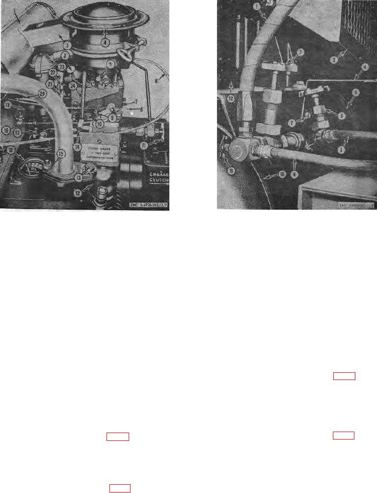
Figure 8. Air receiver controls.
14
Throttle bracket
15
Hex nut, 5/16-20 (2 rqr)
16
Oil pressure gage
above the carburetor. It is a pump-type lever used to
17
Oil pressure relief adjusting screw
prepare the engine for initial starting by filling the
18
Governor linkage
carburetor with gasoline.
19
Governor arm
20
Sensitivity adjusting screw
35. Air Receiver Pressure Gage
21
Governor speed adjusting nut
The air receiver pressure gage (12, fig. 9) is located
22
Cap screw, 3/8-16 x 21/2 in. Ig (2 rqr)
on the compressor side of the unit on the manifold. The
23
Crankcase breather
air receiver pressure gage is graduated from 0 to 300
24
Fuel line
psi. The gage should show a pressure of 150 to 175 psi
for proper operation of the lubricating unit.
Figure 7. Engine controls and instruments.
36. Air Receiver Safety Valve
33. Heater Control Switch
The air receiver safety valve (13, fig. 9) is located
The heater control switch (9, fig. 9) is located on
on the engine side of the air tank at the top. It is a
the lower left-hand corner of the heater control panel. It
spring-loaded
valve
which
releases
is a toggle-type switch which turns the heater on to HI,
LOW, and OFF.
34. Fuel Pump Primer Lever
The fuel pump primer lever (3, fig. 9) is located on
the engine at the side of the air cleaner and
19

