1
Compressor intake muffler
7
Heater slide tray
13
Air receiver safety valve
2
Safety valve
8
Heater control switch
14
Engine exhaust director handle
3
Fuel pump primer lever
9
Reset button
15
Cap screw, 5/16-18 x 1 in. Ig (2 rqr)
4
Thermostat
10
Press-to-test lamp
16
Bracket
5
Heater bleeder valve
11
Center toolbox
17
Quick coupling
6
Heater
12
Air receiver pressure gage
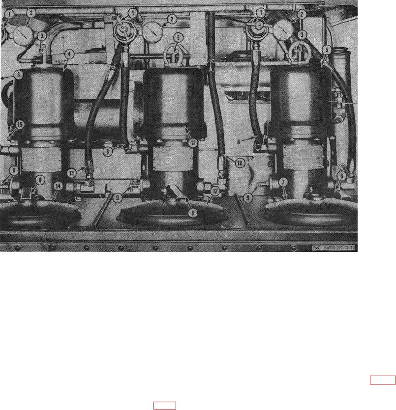
Figure 9. Lubricating unit controls and instruments, compressor side.
excess air pressure from the receiver at a
exhaust gases through a hose to atmosphere outside
predetermined setting of 200 pounds. If for any reason
the unit, when heating of grease and oil is not desired.
the pressure need be released before the excess
pressure point has been reached, grasp the ring located
38. Air Regulators
on the safety stem, and pull upward to open the safety
Air pressure and speed, to the three lubricating
valve and allow the air to escape.
pumps, are controlled by the air regulators (1, fig. 10)
mounted on the air line between the air receiver and the
37. Engine Exhaust Director Handle
lubricant pumps. The exact air pressure to operate the
The engine exhaust director handle (14, fig. 9) is
pumps must be determined by the operator, based upon
used either to direct heat from the engine exhaust into
volume or delivery rate required. To increase air
the lubricant compartment heat chamber, or direct
pressure to pumps turn regulator handle clockwise.
20

