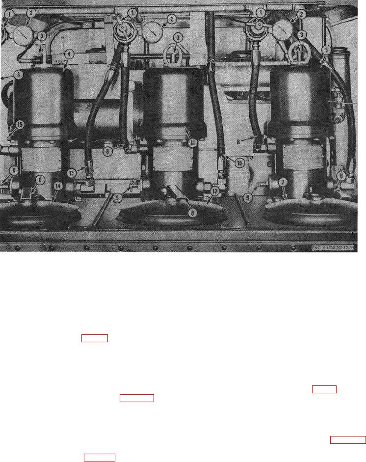
1
Pressure regulator valve
6
Fill cover handle
11
High-pressure pump
2
Air pressure gage
7
Fill cover, engine oil
12
Grease, GAA, fill cover
3
Condensate valve
8
Air line, regulator-to-pump
13
Gear lubricant line
4
Gear oil pump
9
Circulating valve
14
Gear lubricant fill cover
5
Engine oil pump
10
Grease, GAA, line
15
Oiler
Figure 10. Lubricating unit controls, pump end.
on the lower pump housing and permits the bypassing
39. Air Pressure Gage
and circulating of lubricants with the pump returning
The air pressure gages (2, fig. 10) are mounted on
directly into the lubricant compartment.
To open
the regulators. There is a gage for each of the three
circulating valve turn the handle counterclockwise two
pumps, and each is graduated to read from 0 to 200 psi.
full turns.
Each gage registers the amount of air pressure to its
respective pump.
42. Reel Brake
A hand-operated reel brake (16, fig. 11) is mounted
40. Condensate Valve
on the hub of each hose reel to permit locking of the
The manual condensate valve (3, fig.
10) is
hose reels at any position during operation or after
mounted on the top of each pump, and is used to
operation. The reel brake is a lever-type control.
discharge accumulated moisture from the pump air
motor after operation, by turning the handle
43. High-Pressure Control Valve
counterclockwise.
A high-pressure control valve (10, fig. 11) is
mounted on the engine oil reel, and on the gear oil reel.
41. Circulating Valve
Depress
the
trigger
on
the
high-pressure
The circulating valve
(9,
is
mounted
21

