(3) Replace connection fittings if threads are
(4) Disconnect the oil line at the oil line elbow
damaged.
(10).
c. Installation.
(5) Remove the oil pressure gage (13) and
bracket (12) from the air shroud (4, fig.
(1) Install the oil pressure gage (13, fig. 31)
on the air shroud (4, fig. 12).
b. Cleaning, Inspection, and Repair.
(2) Connect the oil line (8, fig. 31) to the oil
line elbow (10).
(1) Clean all parts using an approved
cleaning solvent.
(3) Connect the air shroud to its proper
position (par. 122).
(2) Replace the oil pressure gage if the glass
is cracked or broken, and the gage does
(4) Install the right-side engine air shroud
not register properly.
Section IX. COMPRESSING UNIT
130. Description
The compressor on the lubricating unit is a two-stage,
16 cfm unit, with a disk-type valve system. The twin-
cylinder construction gives a higher discharge pressure
with less consumption of power.
A splash-type
lubrication system provides adequate lubrication, even if
the oil level in the reservoir is low. The compressor is
equipped with an automatic pressure control which
unloads the compressor through the auxiliary unloader,
when the tank pressure has reached 175 psi, and allows
compression to resume when the pressure has dropped
to 145 psi. A centrifugal unloader, operating from the
crankshaft automatically opens a valve releasing the
head pressure, when the compressor stops, and closes
when compression is resumed. A trouble control,
connected to the automatic pressure switch unloader
provides automatic reduction of engine speed during the
compressor unload periods.
A manually operated
shutoff cock connected to the inlet of the throttle control
provides manual elimination of this automatic speed
reduction during cold weather operation.
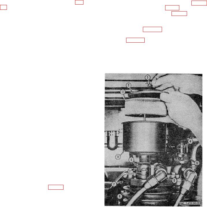
131. Intake Muffler
a. Removal and Disassembly.
(1) Unscrew the wingnut (3, fig. 32) from top
of the intake muffler.
(2) Remove the cover (2) and the filter
element (1) from the reservoir bowl (9).
(3) Unscrew the reservoir bowl (9) at the
1
Filter element
6
Cylinder
2
Cover
7
Cylinder head
muffler adapter (8).
3
Wingnut
8
Muffler adapter
b. Cleaning, Inspection, and Repair.
4
Safety valve
9
Reservoir bowl
(1) Clean all parts, using an approved
5
Elbow, 3/4 in.
cleaning solvent. Make sure all dirt,
Figure 32. Servicing compressor intake muffler.
grime, and sediment are removed from
the bowl.
70

