j. Tighten the setscrew (3) securely, and install the
cover plate (13, fig. 20).
129. Oil Pressure Gage
a. Removal.
(1) Remove the air shroud (4, fig. 12).
(2) Remove the right-side engine air shroud
(3) Carefully pull the blower housing straight
forward to the limit permitted by the oil
gage flexible line (8, fig. 31).
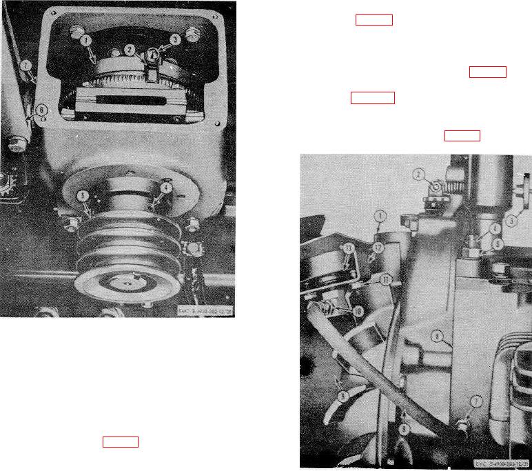
1
Adjusting ring
2
Lockspring
3
Setscrew
4
Socket HD screw, 5/16 x 7/16 in. lg (2 rqr)
5
Pulley
6
Clutch lever
7
Clutch housing
Figure 30. Clutch adjustment.
ring setscrew (3, fig. 30) and lockspring (2) are
at the top of the ring (1).
d. Loosen the adjusting ring setscrew (3) until the
1
Blower wheel
adjusting ring (1) is free to turn.
2
Sensitivity screw
e. Turn the adjusting ring (1) to the right
3
Governor speed adjusting nut
(clockwise) until the toggles can not be locked over
4
Oil pressure relief adjusting screw
center. Use a screw driver (or similar tool with a long
5
Oil pressure relief adjusting screw locknut
heavy shank).
6
7
Oil line connection at crankcase
f. Loosen the adjusting ring (1) a notch or two at a
8
Oil line
time until the toggles can be locked over center with a
9
Witness mark
very firm pull on the engaging lever (6).
10
Oil line elbow
g. Securely tighten the adjusting ring setscrew (3).
11
Nut, No. 12-24 (2 rqr)
12
Bracket
h. Start the engine and work the clutch lever (6)
13
Oil pressure gage
back and forth several times, allowing the clutch to pick
Figure 31. Oil pressure gage removal.
up load but not to lock over center.
i. Stop the engine, loosen the setscrew (3) and
tighten the adjusting ring (1) two or three notches for
final adjustment. Be sure the toggles lock over center at
final adjustment.
69

