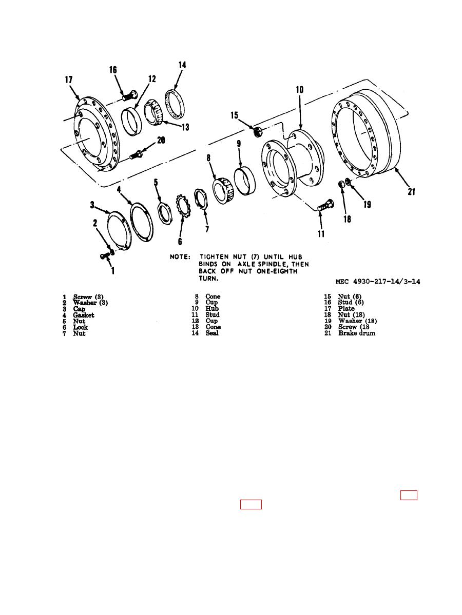
reassembly and installation.
Section XIV. SERVICE BRAKES, HYDRAULIC BRAKE SYSTEM,
AND AIR BRAKE SYSTEM
the towing vehicle. The air reservoir provides
3-75. General
a supply of air for quick application.
The brakeshoes are fitted with riveted lining.
Each brakeshoe is anchored loosely to the back-
ing plate so it can expand and contract without
Cylinders
binding. Each wheel has two wheel cylinders
a. Adjustment.
secured to the backing plate. The wheel cylin-
(1) Release air pressure by opening
ders are actuated hydraulically to give an equal
draincock on air reservoir.
pressure to all brakeshoes. When compressed
(2) Jack the trailer and block it so the
air is admitted to the brake chamber, the dia-
wheels can be turned by hand.
phragm push rod in the brake chamber ac-
tuates the master cylinder piston which fur-
(3) Turn the lower adjusting stud (fig.
nishes hydraulic pressure to apply the brakes.
The brake relay valve controls the trailer
contact brakedrum with slight drag when drum
brakes and automatically applies the trailer
is rotated by hand. Then turn stud clockwise
brakes in event the trailer breaks away from
to allow drum to rotate freely.


