TM 9-4310-397-14
6-10. CONNECTING ROD, PISTONS, RINGS, AND LINERS AND CYLINDER BLOCK INSPECTION AND
REPAIR. - Continued
(2)
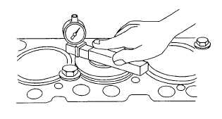
Measure cylinder height (Figure 6-69). Use a dial indicator and gauge (item 22, section III, appendix B).
NOTE
Variations in measurement readings may occur within one cylinder and/or
between adjacent cylinders.
Figure 6-69. Measure Cylinder Height
(a)
Measure each liner in four places, approximately at 1, 5, 7, and 11 o'clock positions as viewed from
the rear of the engine (flywheel end). Record all measurements. Liner height Specifications are as
follows:
1
Liner height above block 0.0004 - 0.004 in. (0.01-0.10 mm). NW
2
Maximum permissible difference between readings within one cylinder or between adjacent
cylinders 0.002 in. (0.06 mm).
3
If liner height is less than minimum specified, one liner shim may be installed on bottom of liner
flange. Two sizes of shims are available 0.002 in. (0.05 mm) and 0.004 in. (0.10 mm).
(b)
Remove cap screws and washers securing liners to cylinder block.
NOTE
Each cylinder liner must be reinstalled in cylinder bore from which it was
removed.
(c)
Number cylinder liners and pistons. Stamp front of liner to assure correct assembly. Do not stamp
liner flange; stamp on fire dam only.
6-58


