b. Remove the shim (3), spring (4), guide (5), ball
(6), and seat (7) from the crankcase (14).
c. Unscrew the strainer retainer (8) and remove the
preformed packing (9) from the strainer retainer.
d. Remove the spring (10) and strainer (11) from
the crankcase (14).
e. Unscrew the cap (12) from the connector (13);
unscrew the connector from the crankcase.
38. Cleaning
a. Use a soft brush to clean apertures, slots, and
holes, paying particular attention to the crankcase and
crankshaft passages. Remove carbon deposits in the
heads and valves.
b. Clean all metallic parts except the crankcase
(13, fig. 15) in ultrasonic cleaner. Blow strainers dry with
clean, dry, compressed air.
c. Use an oil base ultrasonic cleaner to clean the
crankcase (14, fig. 16).
Caution
Under no condition should a water base
ultrasonic cleaner be utilized to clean any cast
iron component.
39. Inspection
a. Inspect all parts visually for obvious signs of
wear or damage.
b. Inspect all internal and external threads and
discard any part having more than two damaged threads
in any one location.
c. If the crankshaft has been disassembled,
measure the diameters of the shaft. The front bearing
seating surface should be between 1.2501 and 1.2505 in
O.D. The rear bearing seating surface should be
between 1.5749 and 1.5753 in O.D. The keystone
assembly seating surface should be between 0.8750 and
0.8753 in O.D.
d. If
the
keystone
assembly
has
been
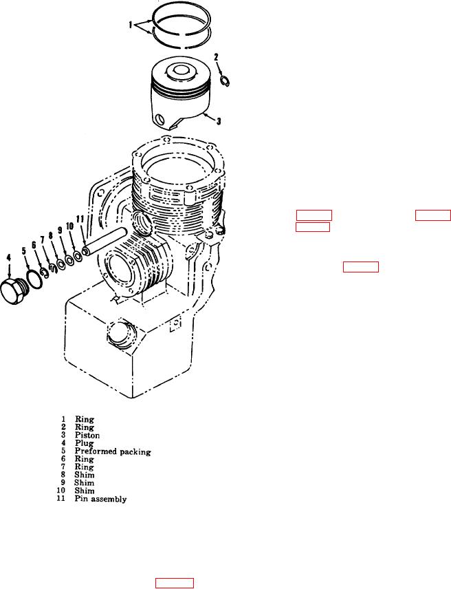
Figure 14. First stage piston, exploded view.
disassembled, measure the diameters of the keystone
bores. The crankshaft bore of the keystone assembly
bearing (7) from the crankshaft using a bearing puller or
should be between 0.8759 and 0.8763 in I.D. The first
brass drift and hammer.
stage piston pin bore of the keystone assembly should
be between 0.5008 and 0.5012 in I.D.
37. Crankcase Section Disassembly (fig. 16)
e. Inspect the valves and valve seats to see
a. Unscrew the spring retainer (1) and re 24 move
the preformed packing (2) from the spring retainer.
AGO 5548A
24

