
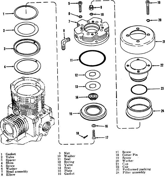
Figure 13. First stage valve, exploded view
e. Remove the gerotor assembly (15), pin. (12),
c. Remove the wave washer (5) and oil seal (6)
from the rear of the crankshaft (11). Remove the ring
and plate (14) from the front of the crankshaft.
(18), oil seal (17), and the preformed packing (16) from
f. Press or drive the two rollpin assemblies (9) out
the front of the crankshaft.
of the keystone assembly (23) and remove the upper
d. Unscrew the three screws (19) and washers (20
keystone (8) and lower keystone (10) from the
and 21) and using 5/32-inch socket wrench, remove the
crankshaft (11).
crankshaft, bearings and gerotor assembly from the
Note.
The keystone assembly consists of matched
parts; keep together and separate from similar
assemblies of other compressors.
g. Remove the front bearing (13) and rear 23
AGO 5548A
23