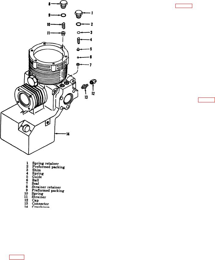
41. Crankcase Assembly (fig. 16)
a. Screw the connector (13) securely into the
crankcase (14) then assemble the cap (12) to the
connector.
b. Position the preformed packing (9) on the
strainer retainer (8).
c. Position the strainer (11), spring (10), into the oil
return port in the crankcase (14); secure the strainer
retainer (8) into the oil return port and tighten securely.
d. Position the preformed packing (2) onto the
spring retainer (1).
e. Position the seat (7), ball (6), guide (5), spring
(4), shim (3) into the oil pressure relief port in the
crankcase (14); screw the spring retainer (1) into the oil
pressure relief port and tighten securely.
42. Keystone-Crankshaft Assembly (fig. 15)
a. Using an arbor press, press the front bearing
(13) and rear bearing (7), one at a time, onto the
crankshaft (11) until the bearings shoulder.
Caution
Exert pressure on the inner race of the
bearings only, to prevent damage to the
bearing's rotating elements during installation.
b. Position the upper keystone (8) and lower
keystone (10) ("F" on both components facing the fan
end on the compressor) onto the keystone bearing
surface of the crankshaft (11); secure in place by
pressing the two rollpin assemblies (9) into the keystone
bearing surface of the crankshaft; press the two rollpin
assemblies into the keystone assembly (23). The gaps
in the two rollpin halves should be oriented 180 apart
during installation and pressed flush with the keystone
assembly surface.
Note
Figure 16. Crankcase, exploded view.
The upper and lower keystone are selective fits
and are not interchangeable with similar parts.
40. Lubrication
During assembly if the keystone assembly
a. Apply oil (OE-0) to all preformed packings.
binds on the crankshaft, it may be loosened by
tapping the upper and lower keystone with a
b. Apply oil (OE30) to all threaded areas.
plastic or rawhide mallet.
c. Apply oil (OE-30) to all wear surfaces.
c. Position the plate (14) onto the crankshaft (11) in
d. Apply oil (OE-30) to the front and rear bearings
front of the front bearing .(13).
(7 and 18, fig. 15).
d. Insert the pin (12) into the crankshaft (11) and
position the gerotor assembly (15) onto the pin.
AGO 65348A
26

