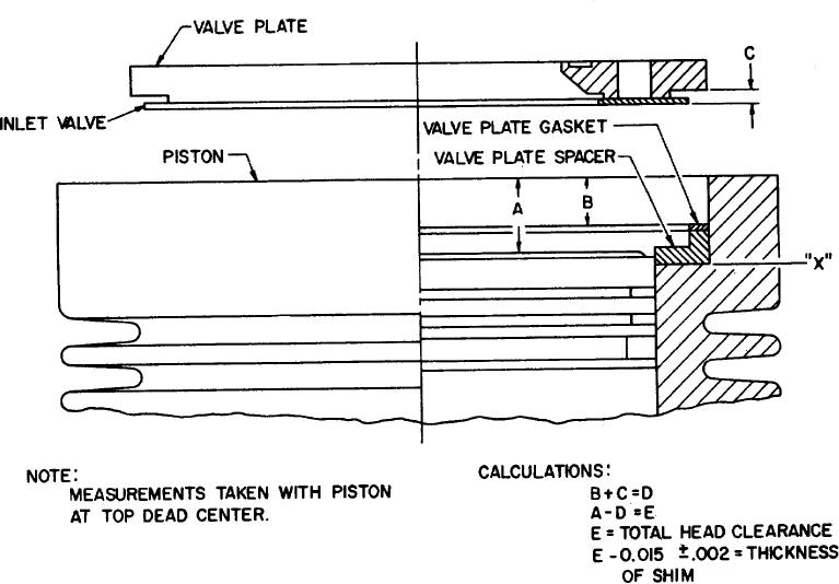
Figure 17. First stage head clearance.
f. Position the intake valve (2) on the intake valve
k. Position the preformed packing seal (11) in the
seating surface on the valve plate (15) and measure the
groove in the head assembly (7)
distance from the valve to the flat on the valve plate.
l. Position the discharge valve spring (12),
Record this value as the "C" value.
discharge valve (13) and discharge valve se (14) on the
g. Determine the total available first stage head
head assembly (7) and secure An place by using the
clearance by adding the values of "B" and "C" obtaining a
screw (17), gasket (16), washer (10), and nut (9). Apply
sum value equal to "D".
a torque to the nut until the hole in the screw is alined
Subtract the value of "D" from the value of "A" and obtain
with the hole if the nut. Position the cotter pin (18) into
a remainder value of "E. This value "E" is the total head
the alined holes and bend the cotter pin over the nut and
clearance for the first stage.
along the screw. The maximum permissible torque on
the nut is .8 pound-feet.
h. Subtract the required first stage head clearance
of 0.015 + .002 inches from the "E" value and record this
m. Position the head assembly (7) on the valve
value as the thickness of shim (4).
plate (15) and orient the outlet port in the head assembly
i. Remove the spacer (3) and gasket (1) from the
120 to the left from the dead front point on the first
first stage cylinder bore.
stage cylinder and aline the screw holes in the head
assembly with the screw holes in cylinder.
j. Position the shim (4), spacer (3), intake 28 valve
(2), gasket (1), and valve plate (15) into the first stage
cylinder bore.
AGO 5548A
28

