
n. Center the discharge valve (9) and the discharge
valve spring (10) on the valve plate (8) and then position
the head assembly (14) on the valve plate so that the
inlet port is oriented to the front of the compressor
assembly and the screw holes in the crankcase (14, fig.
16), plunger and cylinder assembly (4, fig. 11)', and the
head assembly are in alinement. Secure the third stage
section with the four screws (16) and washers (15) and
apply a torque to screws between 60 to 65 pound inches
using the torque wrench and 9/64-inch socket wrench.
o. Assemble the second stage relief valve (17) to
the inlet port and the elbow (13) to the discharge port of
the head assembly (14).
Note
Final orientation of the elbow (13) and the
second stage relief valve (17.) is determined
during the assembly of the second stage
intercooler anti the aftercooler.
p. Position the preformed packing (18) and the
fourth stage plug (19) on the fourth stage port in the
crankcase (14, fig. 16) and secure with the four screws
(22, fig. 11) and washers (20). Apply a torque between
50 and 60 pound-inches to the screws using a 3/16-inch
socket wrench. Secure the screws after assembly using
a lockwire (21).
47. Testing
Prior to normal operation and use of the
compressor group in the overall unit, various test runs of
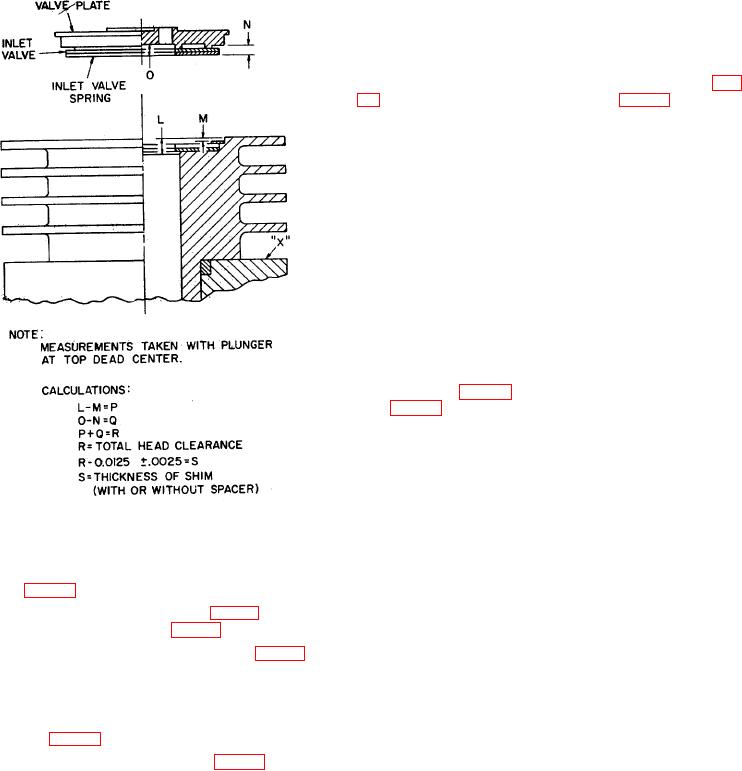
Figure 19. Third stage head clearance.
the compressor group must be accomplished. The type
of test run performed on the compressor group is
i. Remove the plunger and cylinder (4) from the
dependent upon the scope of replacement performed
crankcase (14, fig. 16).
during overhaul of the compressor group. In the event
j. Position the preformed packing (1, fig. 11) in the
that replacement of the crankcase, first stage piston, first
third stage port in the crankcase (14, fig. 16).
stage piston rings, second stage plunger or second
stage plunger rings is required, a four-hour special run is
k. Position the proper thickness of shim (2, fig. 11)
to be performed. If the third stage cylinder and plunger
with or without the spacer (3) to give the proper third
assembly is replaced in the compressor group the
stage head clearance, on the lower side of the third
performance of an eight-hour special run is required.
stage plunger and cylinder assembly (4) and position the
The replacement of any other pneumatic system parts
plunger and cylinder assembly in the third stage port in
require a one-hour minimum special run.
the crankcase (14, fig. 16).
l. Position the inlet valve spring (5, fig. 11), inlet
Caution
valve (6), gasket (7) and valve plate (8) on the plunger
Performance of the special runs are
and cylinder assembly (4).
accomplished when the compressor is
m. Position the gaskets (11 and 12) in the grooves
complete with coolers, brackets, fan and fan
on the head assembly (14).
guard and mounted on the test stand. The test
stand is used to perform all special runs.
AGO 5548A
31