
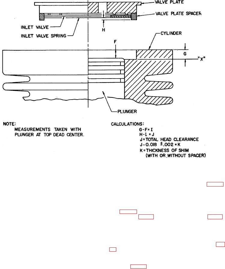
Figure 18. Second stage head clearance.
Secure the head assembly to the first stage cylinder with
a. Determine the thickness of shim (15, fig. 12)
the six screws (5) and washers (6). Apply a torque of 30
required to give a proper second stage head clearance
to 35 pound-inches to the screws using the torque
between 0.016 and 0.020 inches as described in b
wrench and 9/64-inch socket wrench.
through h below. Refer to figure 18.
n. Position the preformed packing (23) in the
b. Insert the second stage plunger subassembly
groove on the cap (22).
(17, fig. 12) into the 2d stage cylinder bore of the
o. Position the filter assembly (24), cap (22) and
cap (21) on the head assembly (7) and secure with four
using a suitable size hexagonal bar stock, so that the
screws (19) and washers (20). Apply a torque to the
plunger is at top dead center.
screws between 17 and 22 pound-inches.
c. Using a depth micrometer, measure the distance
p. Assemble the outlet elbow (8) to the outlet port
from the flat surface of the second stage cylinder to the
of the head assembly (7).
top of the second stage plunger subassembly (17, fig.
12). Record this value as the value "F."
Note
d. Measure the distance from the flat surface of the
second stage cylinder to the flat seating surface of the
Final orientation of the elbow is not
shim (15, fig. 12) in the second stage bore. Record this
determined until assembly of the first stage
value as the value "C."
intercooler.
e. Position the inlet valve (11) on the inlet 29
45. Second Stage Assembly
AGO 5548A
29