TM 3-1040-263-34
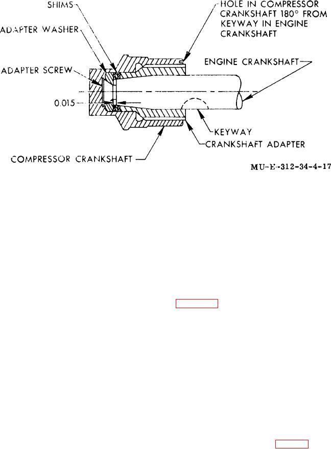
Figure 4-17. Crankshaft-adapter shim determination, and
compressor crankshaft and engine crankshaft orientation.
Section IX. RUN-IN, BREAK-IN, AND PERIODIC TESTING
the bottom of the drive mounting flange of the crankcase.
4-39.
General
A pressure gage capable of measuring 2, 000 psi and a
relief valve must be attached to the water separator
General support maintenance personnel are authorized
outlet to permit measurement and adjustment of the
to perform compressor run-in, break-in, and periodic
compressor output. The stage responsible for blowby
testing. The type of test or test run to be performed
can be detected by decreasing delivery pressure of the
depends on the scope of replacement, performed during
compressor to the rated delivery pressure of each stage
repair or overhaul of the compressor group. Special
(para 1-4a (1)), and noting at which delivery pressure
break-in runs are performed when compressor repair is
the blowby falls off. Excessive blowby will probably be
completed and replacement is not as extensive as
caused by the stage with the next higher delivery
overhaul. Replacement of first- or second-stage rings
pressure; e.g., if the blowby falls off with a delivery
requires at least 1-hour minimum break-in run at 2, 500
pressure of 500 psi, corresponding to rated second-
rpm with 1, 950 to 2, 050 psi delivery pressure or until
stage pressure, the responsible stage is probably the
blowby is 0 3 cubic feet per minute or less. Replacement
third stage
of any other compressor I, art requires a 1-hour
minimum break-in run and a visual check.
4-40.
Twelve-Hour Overhaul Run-In
a. Test Stand. During run-in, break-in, and
The 12-hour overhaul run-in is performed
after
periodic testing, the compressor must be installed in a
completion of an overhaul of the compressor.
test stand capable of operating the compressor from 0 to
3, 600 rpm. A gasket seal must be maintained at the
a. Fill the oil sump to the required level with
compressor-to-test stand connection to permit blowby
compressor oil ('TM 3-1040-263-12).
measurements.
b. Remove cap (2, fig. 4-4) and install a 0 to
Blowby Measurements.
Measure using a
b.
150 psi gage to the discharge side of the oil pump.
flow rate meter attached to the port at
4-28

