TM 5-4310-227-15
14
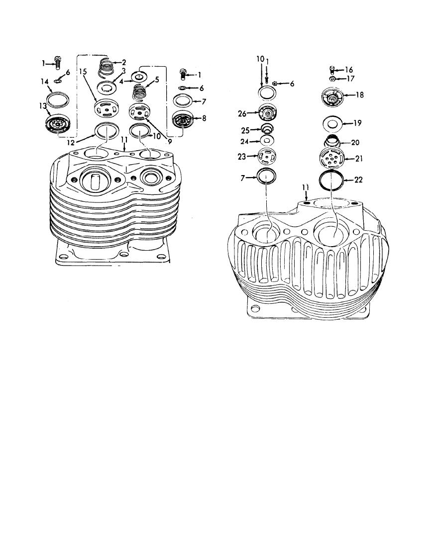
Gasket, copper, 1 23/32 in.
1 Screw, cap, rd-ht, slotted
Low-pressure intake valve seat
15
2 Low-pressure intake spring
16
Screw, 1/4-28 X 3/8 in.
3 Low-pressure intake valve disk
17
Washer, lock, ET, 1/4 in.
4 High-pressure intake disk
18
Low-pressure exhaust valve seat
5 High-pressure intake spring
Low-pressure exhaust valve disk
19
6 Washer, lock, ET, No. 10 (3 rqr)
20
Low-pressure exhaust valve spring
7 Gasket, copper, 1 1/8 in. (2 rqr)
Low-pressure exhaust valve housing
21
8 High-pressure intake valve seat.
Gasket, copper, 2 1/8 in. od, 5/64 in. thk
22
9 High-pressure intake valve housing
High-pressure exhaust valve seat
23
10 Gasket, copper, 1 1/4 in. (2 rqr)
High-pressure exhaust disk
24
11 Cylinder
High-pressure exhaust spring
25
12 Gasket, copper, 1 1/4 in. (2 rqr)
High-pressure exhaust valve housing
26
13 Low-pressure intake valve housing
(2) Install the copper gaskets (7 and 10)
(5), and the high-pressure intake
and the high pressure intake valve
valve housing (9) on the high-pres-
assembly in the cylinder (11).
sure intake valve seat (8) and secure
(3) P o s i t i o n the low-pressure exhaust
with the lockwasher (6) and the screw
v a l v e d i s k ( 3 ) , t h e low-pressure
(1).
3-70


