TM 5-4310-247-15
b. Speed Adjustment.
(1) Lower receiver pressure to 100 psi by
a. Pressure Adjustment.
bleeding air with a service valve. En-
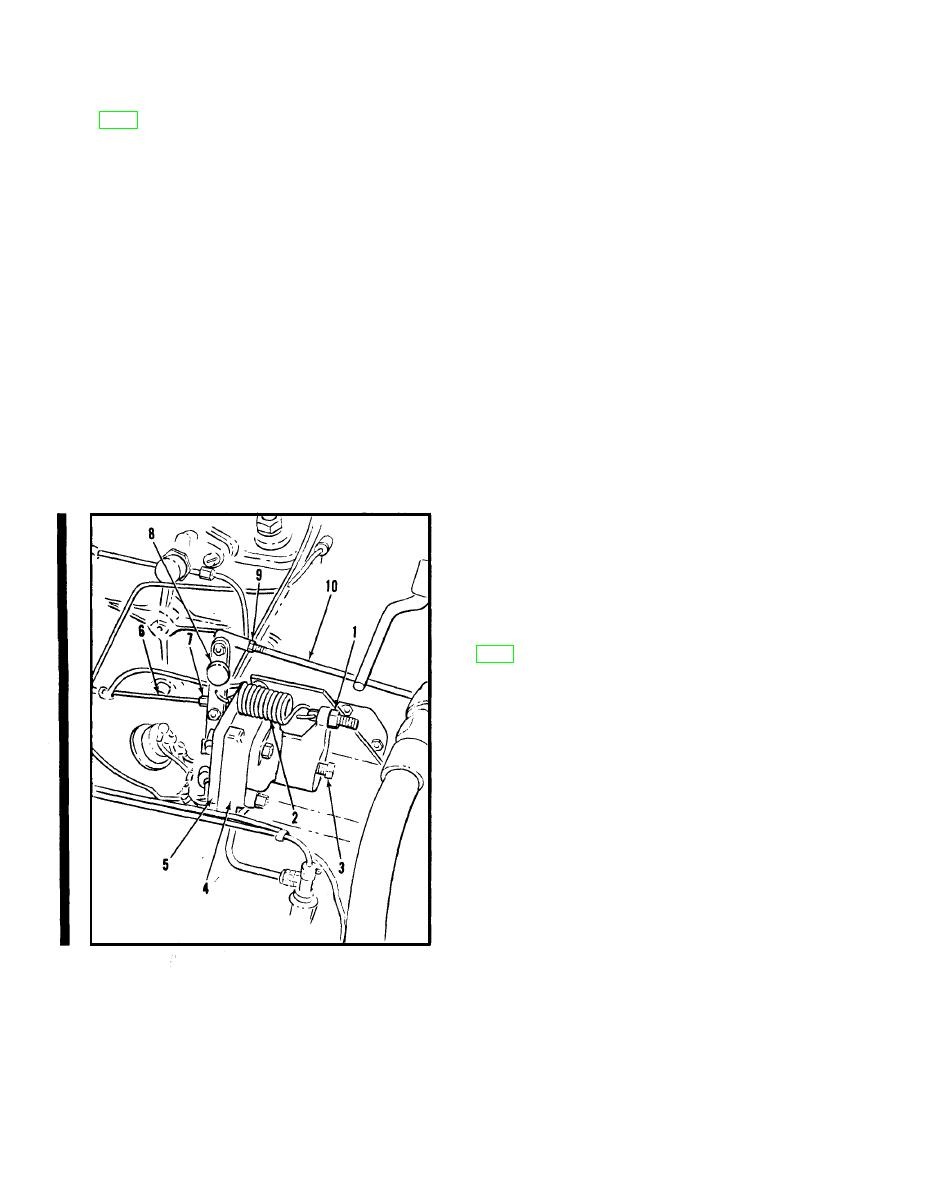
(1) Before starting the engine, turn nut
gine will speed up.
(1, fig. 26) clockwise, finger tight, to
(2) Loosen locknuts (7) on linkage rod
obtain a small amount of tension in
(6) and turn rod to obtain 1,800 rpm.
spring (2) and to hold lever (8)
It may be necessary to change setting
against control diaphragm retainer
of service air valves to maintain 100
(5).
psi during speed adjustment. Tighten
(2) With engine running and thoroughly
locknuts. If lever (8) moves away
warmed up, slowly close all service
from contact with control diaphragm
air valves and allow compressor to
retainer (5) tighten nut (1) several
unload. It may be necessary to loosen
turns or turn screw (3) clockwise
ball joint locknuts (9) and shorten
slightly. If this condition persists after
rod (10) to prevent engine from stall-
lowering the receiver pressure to 90
ing.
psi, report the condition to direct sup-
(3) Turn screw (3) clockwise to raise re-
port maintenance. Practically no air
ceiver pressure to approximately 110
should leak from the bleed hole in the
psi.
body (4) when operating at full speed
and pressures of 100 psi or below.
(3) Close service valves to unload compres-
sor. Loosen locknuts on rod (10) and
turn rod to obtain an idle speed of ap-
proximately 1,050 rpm at 110 psi re-
ceiver pressure. Retighten locknuts.
Note. The engine must be properly tuned,
thoroughly warmed up, with proper grade of
fuel and oil, relatively clean fuel filters end
air filter prior to air control adjustment.
a. General. This valve is placed in the system
to prevent oil from draining back into the com-
pressor during shut-down. Discharge air pres-
sure holds the valve open during operation, per-
mitting oil to circulate through the system.
Upon shutdown, the loss of air pressure allows
the spring-loaded valve to close.
b. Removal.
(1) Refer to figure 28 and remove the oil
control valve.
(2) Remove nipple (2, fig. 27).
c. Disassembly. Refer to figure 29 for dis-
assembly of the oil control valve.
d. Cleaning and Inspection.
(1) Clean all parts with an approved
cleaning solvent; dry thoroughly.
(2) Inspect all parts for wear or damage,
repair or replace if unserviceable.
6 Linkage rod
1 Nut
e. Reassembly. Refer to figure 29 and re-
7 Locknut
2 Spring
assemble the valve.
8 Lever
3 Screw
9 Locknut
4 Air control assembly
f. Installation. Refer to figure 28 and install
10 Linkage rod
5 Diaphram retainer
the valve.
Figure 26. Air control service.
* U.S. GOVERNMENT PRINTING OFFICE: 1992 643-016/60023
44
Change 4


