d. Reassembly. Reassemble the hose reel
assembly as illustrated in figure 30.
e. Installation. Install the hose reel assembly
(37, fig. 17) using screw (24), washers (19),
and nuts (23).
f. Adjustment. Adjust screws (28, fig. 30)
for correct tension on brake halves (29).
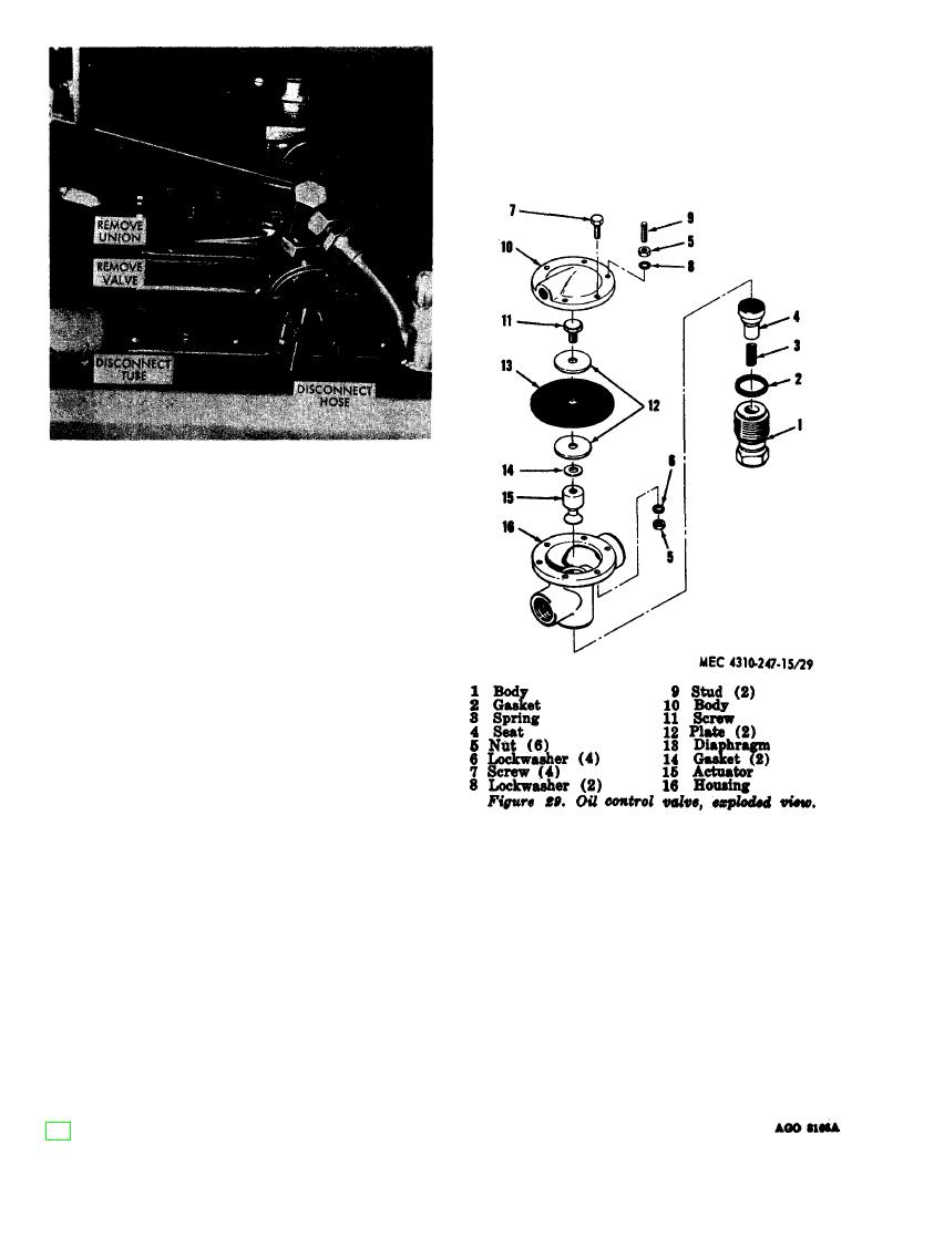
Figure 28. Oil control valve removal.
81. Hose Reels and Fittings
a. Removal. Remove nuts (29, fig. 17),
washers (19), and screws (24); lift out the
hose reel assembly (37).
b. Disassembly. Disassemble the hose reel
assembly as illustrated in figure 30.
c. Cleaning, Inspection, and Repair.
(1) Clean all parts except service hoses in
an approved solvent.
(2) Inspect coil springs for distortion or
lack of tension. Inspect other parts
for breaks, cracks, bends or other dam-
age. Straighten bent parts; weld
breaks or cracks. Replace any de-
fective or unserviceable parts.


