Section XII. VALVE ADJUSTMENT
81.1. General
This section contains valve adjustment and
valve tappet clearance data.
81.2. Valve Adjustment
a. Disconnect rod (10, fig. 26) and spring
(2) from lever (8) to decrease idling speed.
c. After valve adjustment has been completed
TEMPERATURE IS REACHED. REFER
connect rod (10, fig. 26) and spring (2) to
TO PAR. 14.
lever (8).
STEP 2. REMOVE CYLINDER HEAD COVER.
REFER TO FIGURE 18.
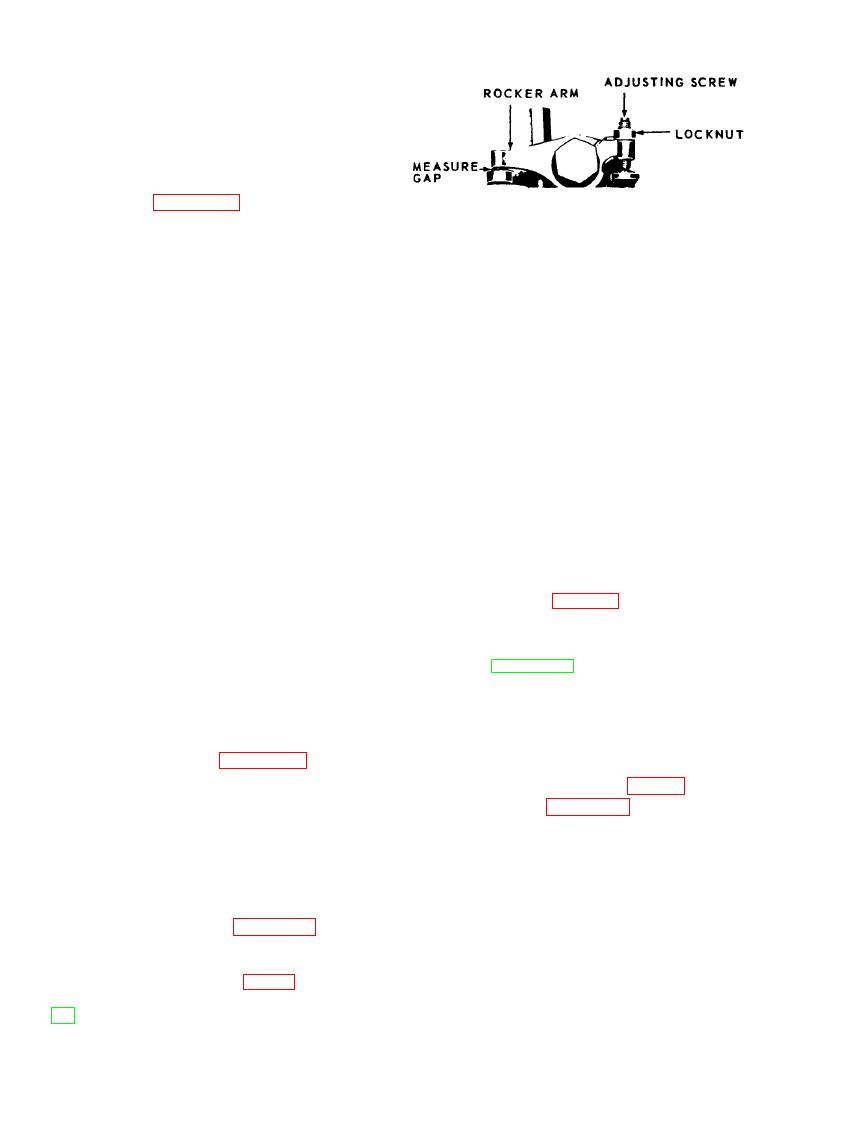
STEP 3. WITH A FEELER GAGE MEASURE CAP
FOR CLEARANCE. PROPER VALVE
TAPPET CLEARANCE IS 0.014 IN.
(HOT).
STEP 4. ADJUST ROCKER ARMS AS NECESSARY
BY LOOSENING LOCKNUT AND TURN-
ING ADJUSTING SCREW CLOCKWISE TO
DECREASE CLEARANCE, AND COUNTER
CLOCKWISE TO lNCREASE CLEARANCE.
STEP 5. TIGHTEN LOCKNUT AFTER ADJUSTING
AND CHECK CLEARANCE.
STEP 6. READJUST AS NECESSARY.
STEP 7. INSTALL CYLINDER HEAD COVER.
REFER TO PAR. 14.
MEC 4310-247-15/30.1
Section XIII. ENGINE LUBRICATION SYSTEM
81.3. Oil Cooler
81.4. Oil Filter
a. Removal.
engine oil cooler.
(1) Remove oil cooler (para 81.3).
b. Cleaning and Inspection.
(2) Refer to figure 30.2 and remove en-
(1) Clean the oil cooler with an approved
gine oil filter.
cleaning solvent; dry thoroughly.
b. Cleaning and Inspection.
(2) Inspect for dents, cracks, breaks, cor-
(1) Clean the engine oil filter assembly,
rosion, or other damage.
except element and gasket, with an ap-
(3) Replace gaskets and damaged mount.
proved cleaning solvent; dry thor-
ing hardware.
oughly.
(2) Inspect all parts for cracks, breaks,
engine oil cooler.
dents, or other damage.
Note. After reinstallation of engine oil cooler bring
(3) Replace gaskets.
cooling system to proper level (para 40).
AGO 8166A


