bring the front shaft in line with hous-
thrust washer (63) and thrust collar
ing hole for inserting the pin, replace
(71) onto the shaft. Position the
the shaft. Drill -inch hole through
thrust washers (63) on the shaft so
the present
-inch hole and drive in
the tangs are in the slots in the hous-
a x 1-inch tempered steel roll pin
ing (86) before installation of shaft.
(fig.48).
If tangs in thrust washers are not in
place, the washers will turn against
(13) Position two aligning studs in bal-
housing causing excessive wear.
ancer oil pump mounting pad. Posi-
(7) When replacing bushings in the forged
tion paper gasket (39, fig. 41), oil
steel counterweight idler (77), press
pump cover (38), lead gasket (37),
in with driver with chamfered end of
gears (43) and oil pump body (36).
bushing toward gear. In order to keep
Caution: Check oil pump idler stud
the oil slots open on the hub, install
(44) so it extends 1
inch above pad
bushing
inch below hub of gear.
face. Also make certain that the oil
Caution: Split bushing must be
hole in the oil pump idler gear in-
pressed in with the split in position
dexes with the oil groove in the idler
as shown in figure 43.
stud. If these do not index gear will
(8) Position counterweight drive gear
freeze on stud causing oil pump
(72, fig. 41) as shown in figure 44. A
failure.
.006-.007 shim and a pilot should be
Note. When replacing oil pump body,
in place when drive shaft (69) is
balancer must be removed from engine
in order to properly position the new body.
being pressed through bushing (78)
To check position rotate the drive shaft (69).
and gear (79).
(14) Assemble hex head capscrews (28 and
(9) Check thrust collar (71, fig. 41) with
31, fig. 41) lockwashers (29) through
shim stock for .003 to .005 end play
oil pump body to balancer housing.
(fig. 45).
Torque to 12 foot-pounds and check
(10) If pin hole in thrust collar (71, fig.
for freeness of pump gears by rotating
41) does not line up when assembled
drive shaft (69). Remove aligning
to .003 to .005 end play, due to wear on
studs, assemble oil relief shield (27)
thrust washer (63) or collar, redrill
and remaining capscrews and lock-
pin hole through collar and shaft at
washers and torque to 12 foot-pounds.
right angles to original hole.
(11) Apply a wedge between bottom of
counterweight drive gear (72) and
housing (86). Tighten the two Nylock
setscrews (66) securely. Stake each
screw in four places and remove wedge
as shown in figure 46.
(12) Press counterweight idler shaft (76,
fig. 41) with gear (72) into housing
(86). For reassembly of original
shaft, align mark on end of shaft with
mark on housing (fig. 47). Position
counterweight idler gear (72, fig. 41)
on shaft so edges of both counter-
weights are in the same plane. To
prevent a mismatch of hole in shaft
with groove in the bushing, press in
counterweight idler shaft with end of
shaft
inch from finished face of
oil pump mounting pad. If, when
mounting, the
-inch dimension
from the end of the shaft does not
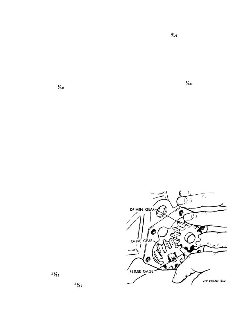
Figure 42.
Gear clearance.
78
AGO 8166A


