(22) Refer to paragraph 115 and install
t h e engine.
(23) Lubricate the engine in accordance
with the current lubrication order.
Note. After assembly and on initial run
at 1,800 rpm, oil pressure should be 30 to
40 psi. If it is below this figure, install
washers in cavity of oil relief plunger. Re-
assemble oil relief plunger spring, oil relief
spring retainer and cotter pin.
(manifold side)
a. Removal and Disassembly. Remove the
external parts on the manifold side of the en-
gine as shown in figure 60.
Note. Provide a clean place to work, and clean the
engine exterior before you start disassembling.
(1) Drain water from engine and discon-
nect radiator outlet hose.
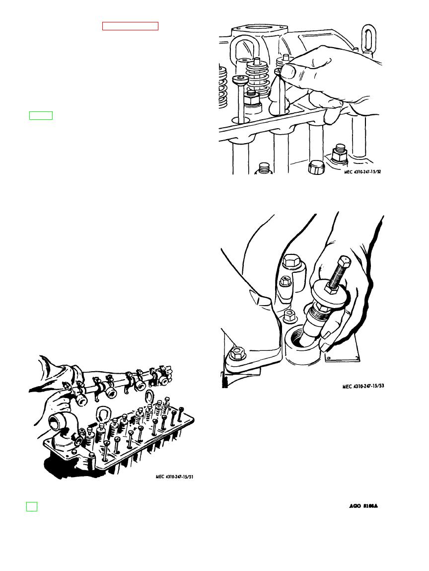
Push rod disassembly.
Figure 52.
(2) Remove cylinder cover (18) by taking
out the screws holding it to the rocker
arm supports. Remove gasket (19).
(3) Remove rocker arm shaft assembly
and push rods (fig. 51). Grip the push
rods and snap them sideways out of
the tappet sockets (fig. 52). This
breaks the hydraulic connection, and
permits lifting the push rods out with-
out disturbing the tappets. (If tap-
pets are lifted out of the guides, they
will have to be reassembled through
the opening in the block when only the
cylinder head is removed for servic-
ing.)
(4) Disconnect the injection and leak-off
lines at both the nozzle and pump con-
Figure 53. Energy cell body removal.
nections and immediately cap the fit-
tinge to prevent dirt from entering.
(5) Loosen and remove the nuts holding
the cylinder head (36, fig. 50) to the
block (69) .
(6) Lift the cylinder head off the engine
and carry it to a clean bench for fur-
ther disassembly. Remove and discard
old gasket (37).
Figure 51. Rocker arm shaft removal.


