ENGINE
Section VI.
(3) Inspect all metal parts for breaks,
bends, nicks, groves, cracks, dents,
(fuel injection side)
obstructions, broken welds, damaged
a. Removal and Disassembly. Remove the ex-
or worn threads, and corrosion. Use
ternal parts on the fuel injection side of the
a fine stone to remove small nicks or
engine as shown in figure 39.
burrs. Replace all damaged parts.
(1) Disconnect the fuel injection lines (6)
c. Reassembly and Installation. Reassemble
from the injection pump (22), and noz-
and install external parts on the fuel injection
zle holders (9).
side as shown in figure 39.
Note. Clean the side of the engine before
(1) Clean carbon and dirt from counter-
disconnecting the injection lines. Use clean
bore and gasket seat in the cylinder
fuel to flush the fittings, so that dirt cannot
head before installing nozzle holder
enter the injection system. As each line is
assembly, as small carbon particles on
removed, plug the pump openings and cap
the nozzles with clean (preferably plastic)
seating surfaces will clog assembly
plugs and caps. Tape the ends of all lines.
and permit blow-up. A reaming tool
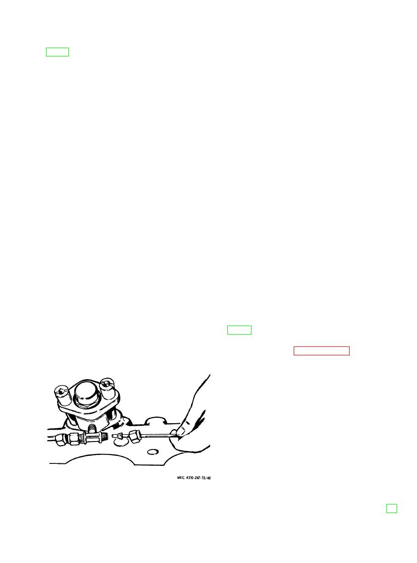
(2) Remove nozzle holders (9) and leak-
or round piece of wood or brass, prop-
off tube assembly (12, 14 and 15). Be-
erly shaped, may be used.
gin with the No. 1 nozzle holder (fig.
(2) Install nozzle holders and leak-off tube
40).
assembly, starting with nozzle holder
Caution: Do not strike nozzle tips
No. 4. When tightening leak-off con-
against hard surface or damage will
nections, always hold the fittings with
result. Nozzle holders should not be
a wrench to keep them from turning
disassembled unless cleaning or other
while tightening the nuts.
service is needed.
screws to 14-16 ft-lb. Pull down evenly in
b. Cleaning, Inspection, and Repair.
three stages, at 5, 10, and 16 ft-lb, respec-
(1) Clean all metal parts in an approved
tively.
cleaning solvent and dry thoroughly.
(3) Remove all caps, plugs and protective
Wipe nonmetallic parts with a clean,
tape, and connect the fuel injection
dry cloth. Clean hose with soap and
lines between the pump and nozzle
water.
holders.
(2) Check line, tube, and hose assemblies
for continuity. Inspect hose for cuts,
worn or weak spots, and deterioration.
a. Removal and Disassembly.
Replace if unserviceable.
(1) Refer to paragraph 115 and remove
t h e engine.
(2) Remove all oil lines which connect
balancer housing to crankcase at both
housing and crankcase ends.
(3) Loosen screws (84 and 85, fig. 41) and
pry the balancer loose from the dowels
(59). Remove screws and balancer.
(4) Remove the nut (51) and washer (52)
from idler gear stud (58) and press
o u t stud.
(5) Remove oil pump wire (9), oil screen
(10), frame (14), screws (25), and
oil relief shield (27).
(6) Remove screws (28 and 30) and re
move oil pump body (36).
Figure 40. Disconnecting nozzle leak-off line.
AGO 8166A


