on crankshaft gear must be in the
lowest position. Mount the complete
balancer assembly to the crankcase
with the capscrews (84 and 85) only
finger tight.
(19) Reconnect all oil lines from balancer
to engine.
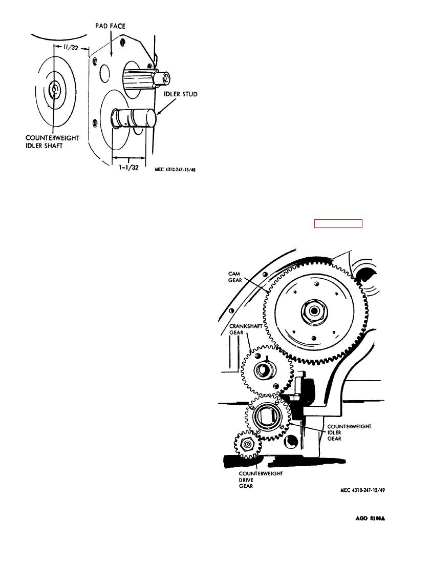
(20) Line up the marked teeth on the
crankshaft gear with the marked tooth
on top of the counterweight idler gear.
Tighten screws holding balancer hous-
ing to engine crankcase to 125 to 130
foot-pounds. Check timing for lineup
after balancer is tightened to be sure
that you are not one tooth off. Check
backlash between crankcase and idler
gear all the way around by rotating
one complete revolution. Crank and
Figure 48. Shaft location dimensions.
balancer idler gear must have .004 to
capscrew and lockwasher assemblies
.0075 inch backlash.
(12). Torque screws to 10 foot-pounds.
(21) Tighten capscrews (84 and 85) to
Assemble oil pump strainer screen
torque as given in paragraph 5.
(10).
(16) Assemble idler gear (64), idler gear
stud (58), spacer (63), and idler gear
bearing (55). Assemble retainer
plate (56) to idler gear with screws
(57). Tighten screws securely and
stake two places in each screw so
metal from gear is driven into screw
slots.
(17) Assemble idler gear assembly (step
15) into housing. Secure with washer
(52) and nut (61). Line up marked
tooth space on idler gear (47) with
marked tooth on counterweight drive
gear (62). Rotate balancer idler gear
to bring marked tooth space on idler
gear and marked tooth on counter-
weight drive shaft gear in line. Due to
the gear ratio of the two gears, the
markings line up only once every 31
turns, so it maybe necessary to rotate
the gears several revolutions. Check
backlash of gears for .004 to .007
clearance in four places. Assemble
lockwasher (61) and nut (61). Torque
nut to 75 foot-pounds (fig. 49).
(18) Turn engine crankshaft until the
marked tooth space on the crankshaft
gear lines up with the marked teeth
on the cam gear. The marked teeth
Figure 49.
Gear alignment.
80


