tive during inspection. Screw the en-
ergy cell body (14) on the end of a
piece of wood, then insert the cell into
the cylinder head, lapping the energy
cell body to the seat.
Note. The seat in the cylinder head must
be gastight, since it is a point at which the
cell is sealed into the head. Any leakage will
cause burning of the surrounding metal in a
short time.
(6) Lap the mating surfaces between the
energy cell caps and the energy cells
to insure an airtight seal.
(7) Position the energy cell bodies (14),
caps (13), and retainers (12) in the
cylinder head assembly (36), and se-
cure with the energy cell plugs (11).
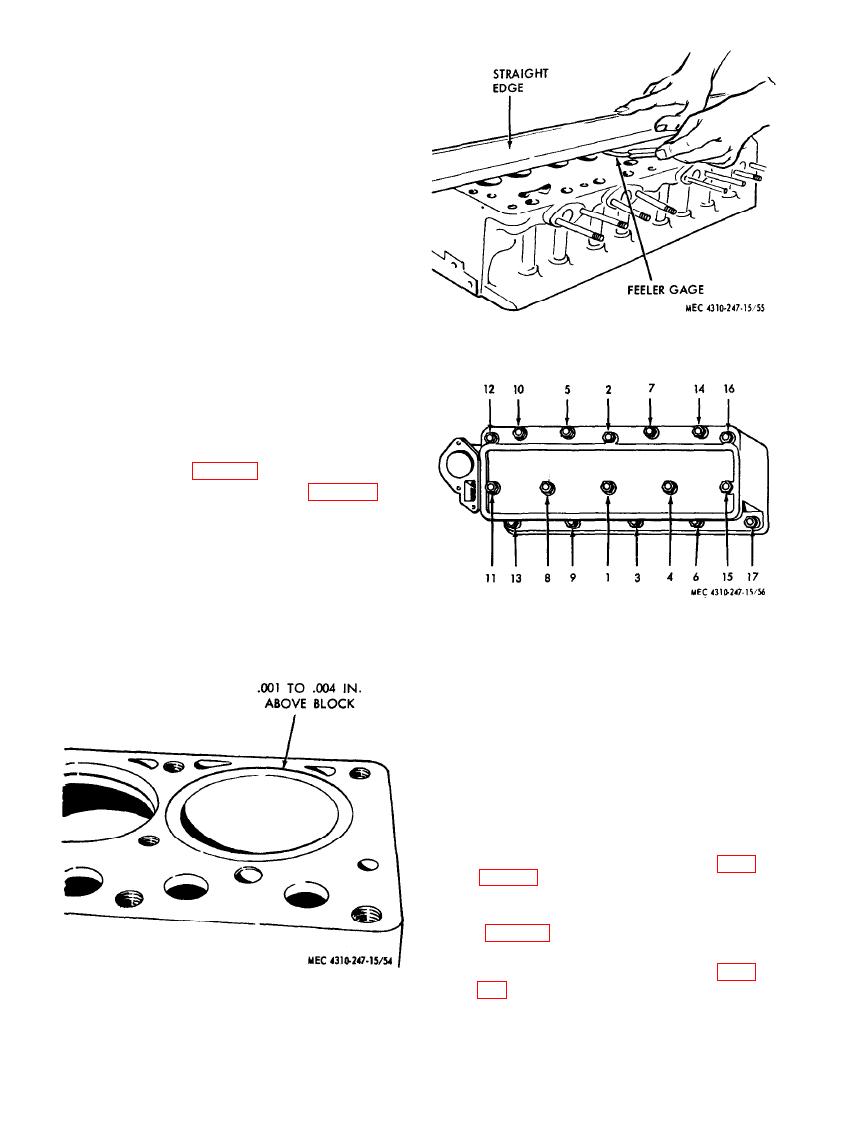
Figure 55. Cylinder head inspection.
Tighten plug, and torque to 100 foot-
pounds.
(8) If it was necessary to remove the fuel
injection nozzle holders in order to
drive the energy cells out of the-cylin-
der head, replace the nozzle holders at
this time (para 130).
(9) Replace valve assemblies (para 134)
and check gasket contact surfaces on
the head (36, fig. 50) and block (69),
making sure they are clean, smooth,
and flat.
Note. Check flatness with straight edge
and feeler gage in three positions lengthwise
and five crosswise (fig. 55). The maximum
Figure 56. Cylinder head tightening sequence.
permissible is .004 inch low in the center
lengthwise, gradually decreasing toward the
ends, and .003 inch crosswise or in localized
low spots. Cylinder head or block must be
resurfaced if these limits are exceeded.
Note. Use new cylinder head gasket (37,
fig. 50). If difficulties are encountered with
gasket sealing, coat both sides of gasket with
heat resisting aluminum paint and assemble
immediately.
(10) Using a chain hoist, lower the cylinder
head assembly (36) evenly over the
studs, then pull all cylinder head nuts
down snug with speed wrench and
tighten with torque wrench.
Note. Refer to the tabulated data of para-
three stages, in the sequence shown in fig. 56.
(11) Connect injection and leak-off lines
(12) Reassemble and install valves, push
rods, and rocker arm assembly (para
Figure
54.
Cylinder
sleeve
reassembly.
AGO 8166A
84


