TM 5-4310-354-14
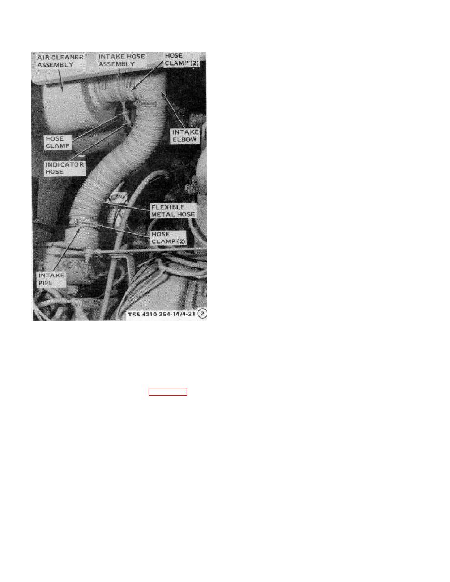
REMOVAL
STEP 1.
LOOSEN HOSE CLAMPS AND REMOVE
FLEXIBLE
METAL
HOSE
FROM
COMPRESSOR
INTAKE
PIPE
AND
INTAKE ELBOW.
STEP 2.
LOOSEN HOSE CLAMP AND REMOVE
INTAKE ELBOW. LOOSEN HOSE CLAMP
AND
DISCONNECT
RESTRICTION
INDICATOR HOSE FROM INTAKE HOSE
ASSEMBLY.
REMOVE RESTRICTION
INDICATOR
HOSE
FROM
THE
INDICATOR.
STEP 3.
LOOSEN HOSE CLAMP AND REMOVE
THE INTAKE HOSE ASSEMBLY FROM
COMPRESSOR AIR CLEANER OUTLET.
ONLY WHEN NECESSARY, REMOVE
INLET PIPE FROM COMPRESSOR.
INSTALLATION
STEP 1.
AS
NECESSARY,
INSTALL
COMPRESSOR INLET PIPE.
INSTALL
INTAKE
HOSE
ASSEMBLY
ON
COMPRESSOR AIR CLEANER OUTLET
AND SECURE WITH HOSE CLAMP.
STEP 2.
INSTALL
RESTRICTION
INDICATOR
HOSE ON THE INDICATOR. CONNECT
INDICATOR HOSE TO INTAKE HOSE
ASSEMBLY STEM AND SECURE WITH
HOSE CLAMP. INSTALL INTAKE ELBOW
TS5-4310-354-14/4-21 (2)
AND SECURE WITH HOSE CLAMP.
STEP 3.
INSTALL
FLEXIBLE
METAL
HOSE
BETWEEN
INTAKE
ELBOW
AND
B COMPRESSOR AIR INTAKE
COMPRESSOR INTAKE PIPE. SECURE
WITH HOSE CLAMPS ON EACH END.
Figure 4-21. Engine and compressor air intake lines, hoses, and fittings, removal and installation (sheet 2 of 2).
(2) Remove the compressor control air hoses
b. Cleaning, Inspection, and Repair.
and fittings as shown in figure 4-22.
(1) Clean all hoses with a clean cloth soaked
with solvent, Federal Specification PD-
WARNING
680, Type II and dry thoroughly. Clean all
fittings in this same solvent.
Dry cleaning solvent, P-D-680, used
to
clean
parts
is
potentially
(2) Inspect fittings for cracks and damaged
dangerous
to
personnel
and
threads.
Inspect hose assemblies for
property.
Avoid repeated and
cuts, fraying, and any other damage to
prolonged skin contact. Do not use
covering. Inspect hose ends for damaged
near open flame or excessive heat.
threads and sealing seats. Check for any
Flash point of solvent is 100 F-130 F
obstructions in hoses and fittings.
(38 C-59 C).
(3) Repair of the air lines, hoses, and fittings
is restricted to replacement of all defective
parts.
4-44


