TM 5-4310-354-14
WARNING
Dry cleaning solvent, P-D-680, used
to
clean
parts
is
potentially
dangerous
to
personnel
and
property.
Avoid repeated and
prolonged skin contact. Do not use
near open flame or excessive heat.
Flash point of solvent is 100 F-130 F
(38 C-59 C).
b. Cleaning and Inspection.
(1) Wipe the instrument panel assembly clean
using a cloth dampened with solvent,
Federal Specification P-D-680, Type II.
Dry thoroughly.
(2) Inspect all instruments and gauges for
damage and loose mounting.
(3) Inspect the control cables for kinks,
TS5-4310-354-14/4-33
breaks, or any other damage.
(4) Inspect all other parts for cracks, breaks,
REMOVAL
distortion, deterioration, damaged threads,
or any other defect.
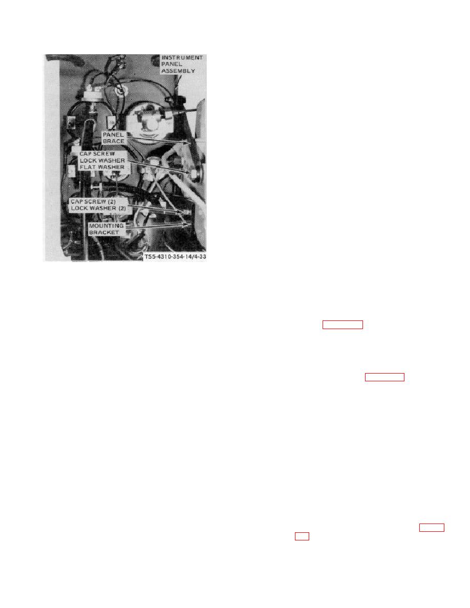
STEP 1.
REMOVE CAP SCREW, LOCK WASHER,
AND FLAT WASHER THAT ATTACH
c. Repair.
Repair of the instrument panel
PANEL BRACE TO ENGINE.
assembly is limited to the replacement of any damaged
component. Refer to figure 4-34 for component removal
STEP 2.
REMOVE CAP SCREWS AND LOCK
and installation.
WASHERS THAT ATTACH INSTRUMENT
PANEL
MOUNTING
BRACKET
TO
d. Installation.
ENGINE.
(1) Install the instrument panel assembly on
STEP 3.
REMOVE THE INSTRUMENT
PANEL
the unit as shown in figure 4-33.
ASSEMBLY FROM THE UNIT.
(2) Connect the idle control cable
and
INSTALLATION
compressor unloader control cable.
STEP 1.
INSTALL THE INSTRUMENT PAN EL
(3) Connect the Quick-Start control cable to
ASSEMBLY IN POSITION ON UNIT AND
the quick start assembly actuating valve
ATTACH TO ENGINE WITH LOCK
lever.
WASHERS AND CAP SCREWS.
(4) Connect the two air cleaner restriction
STEP 2.
ALIGN PANEL BRACE WITH MOUNTING
indicator hoses to the indicators.
HOLE IN ENGINE.
(5) Install the compressor oil temperature
STEP 3.
INSTALL FLAT WASHER BETWEEN
sensing bulb in the air discharge elbow.
ENGINE AND BRACE AND INSTALL LOCK
WASHER AND CAP SCREW TO SECURE
(6) Install the engine water temperature
BRACE TO ENGINE.
sensing bulb in the engine cylinder head.
Service the radiator as shown in figure
Figure 4-33. Instrument panel assembly, removal and
installation.
4-63


