TM 5-4310-354-14
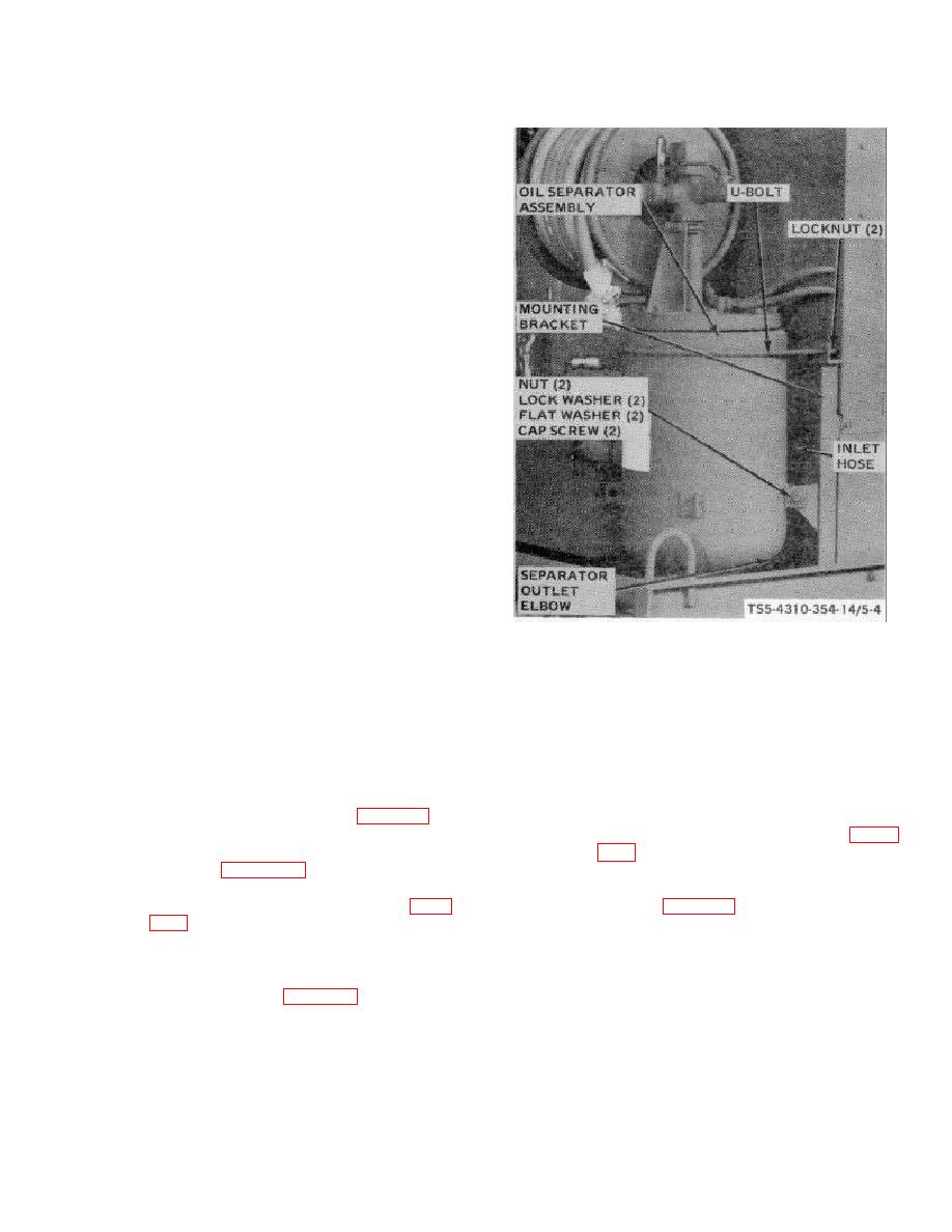
REMOVAL
STEP 1.
DISCONNECT OIL HOSE ASSEMBLY
FROM SEPARATOR OUTLET ELBOW.
STEP 2.
LOOSEN HOSE CLAMPS, DISCONNECT
AND REMOVE SEPARATOR INLET HOSE.
STEP 3.
REMOVE LOCKNUTS AND U-BOLT.
STEP 4.
REMOVE NUTS, LOCK WASHERS , CAP
SCREWS, AND FLAT WASHERS THAT
SECURE
SEPARATOR
TANK
TO
BRACKET.
REMOVE
THE
OIL
SEPARATOR ASSEMBLY.
INSTALLATION
STEP 1.
INSTALL OIL SEPARATOR ASSEMBLY in
POSITION AND SECURE SEPARATOR
TANK TO MOUNTING BRACKET WITH
FLAT WASHERS, CAP SCREWS, LOCK
WASHERS, AND NUTS.
STEP 2.
INSTALL U-BOLT AND SECURE WITH
LOCK NUTS.
TS5-4310-354-14/5-4
STEP 3.
INSTALL SEPARATOR INLET HOSE AND
TIGHTEN HOSE CLAMPS.
STEP 4.
CONNECT OIL HOSE ASSEMBLY TO
SEPARATOR OUTLET ELBOW.
Figure 5-4. Compressor oil separator assembly, removal and installation.
b. Installation.
5-10.
Blowdown Valve Assembly.
(1) Attach a suitable lifting device to the
a. Removal.
compressor oil separator assembly and
install on the unit as shown in figure 5-4.
(1) Disconnect air hose assemblies from
blowdown valve assembly fittings (figure
(2) Connect the air hoses to fittings on top of
separator (figure 4-22).
(2) Remove the blowdown valve assembly as
(3) Install the hose reel assembly (para
shown in figure 5-5.
4-25.f.).
(4) Fill the oil separator tank with proper
grade of lubricating oil in accordance with
LO 5-4310-354-12, figure 3-1.
5-20


