TM 5-4310-354-14
5-11.
Air Compressor Assembly.
a. Removal.
(1) Remove the
engin e
(2) Remove the exterior components on
compressor enclosure as necessary to
gain access to the air compressor (figure
(3) Remove the engine and compressor air
cleaner assemblies (figure 4-15).
(4) Disassemble com pressor enclosure to the
extent necessary to gain access to the
compressor (figure 4-17).
(5) Disconnect and remove compressor air
intake lines, hoses, and fittings (figures
TS5-4310-354-14/5-6
(6) Remove the blowdown valve assembly
REMOVAL
STEP 1.
DISCONNECT
OIL
LINES
FROM
(7) Remove compressor oil temperature
THERMAL BYPASS VALVE ASSEMBLY.
shutdown switch and oil temperature
REMOVE
CAP
SCREWS,
LOCK
sensing bulb. Disconnect and remove oil
WASHERS,
OIL
FILTER-BYPASS
separator inlet hose (para 4-56, 4-70 and
ASSEMBLY AND GASKET.
STEP 2.
REMOVE CAP SCREWS AND LOCK
WASHERS.
CAREFULLY
MOVE
(8) Disconnect compressor unloader control
COMPRESSOR ASSEMBLY AWAY FROM
cable and idle control cable (para 4-63).
ENGINE TO DISCONNECT DRIVE PINS
AND BUSHINGS.
(9) Disconnect speed control rod return
spring. Disconnect speed control rod stop
STEP 3.
LIFT AIR COMPRESSOR OUT OF UNIT.
block from compressor unloader lever
INSTALLATION
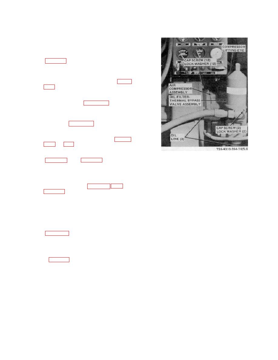
(10) Attach suitable lifting device to eyebolt on
STEP 1.
POSITION AIR COMPRESSOR ON UNIT.
top of compressor stator and remove air
ALIGN COMPRESSOR DRIVE COUPLING
compressor assembly from unit as shown
WITH DRIVE PINS AND BUSHINGS ON
in figure 5-6.
ENGINE FLYWHEEL.
STEP 2.
INSTALL LOCK WASHERS AND CAP
SCREWS
ATTACHING
AIR
COMPRESSOR ASSEMBLY TO ENGINE
FLYWHEEL HOUSING.
STEP 3.
INSTALL A NEW GASKET, OIL FILTER-
BYPASS VALVE ASSEMBLY, ATTACH
ASSEMBLY TO COMPRESSOR WITH
LOCK
WASHERS AND CAP SCREWS.
CONNECT OIL LINES.
Figure 5-6. Air compressor assembly, removal and
installation.
5-22


