TM 5-4310-354-14
b. Installation.
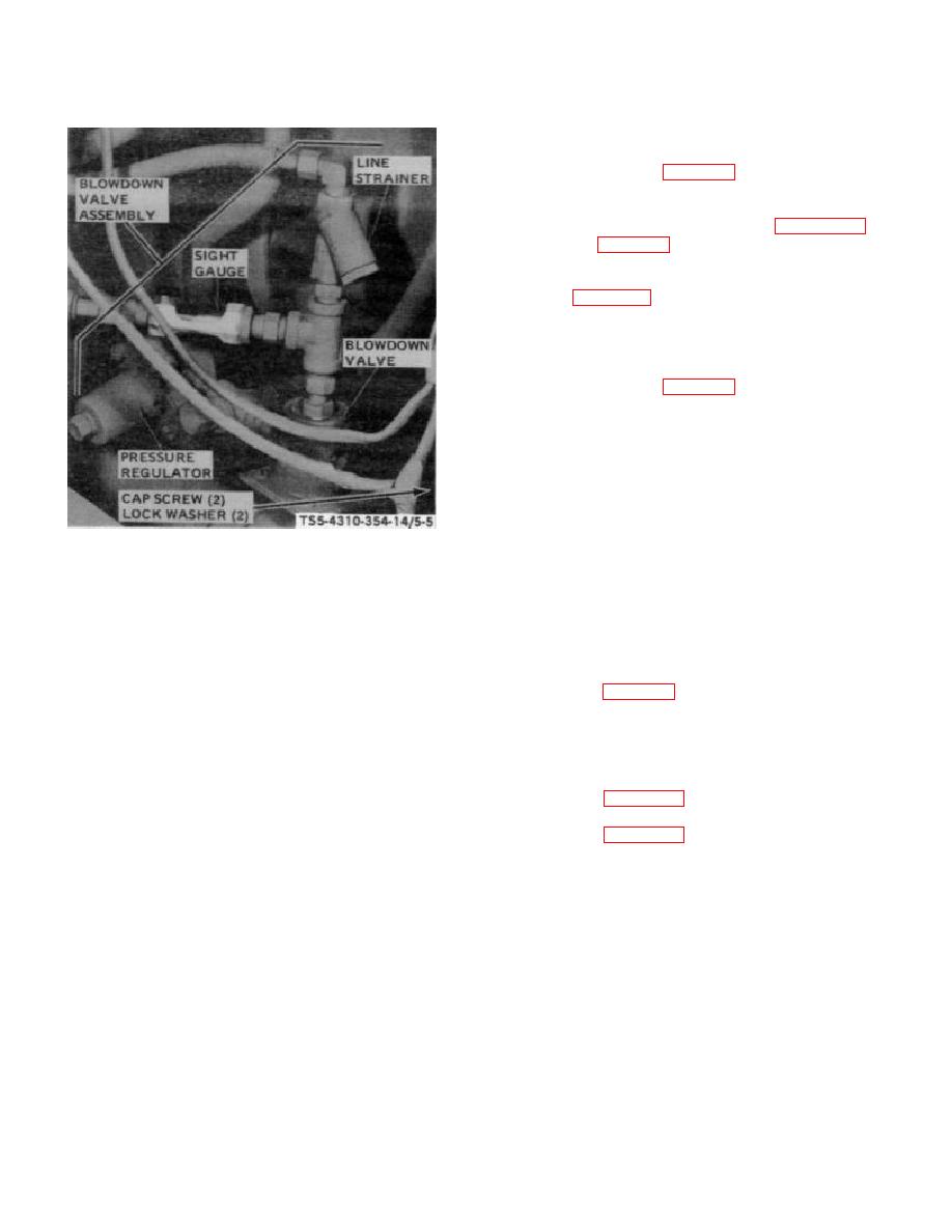
(1) Install the blowdown valve assembly as
shown in figure 5-5.
(2) Connect air hose assemblies to blowdown
valve assembly fittings (figure 4-22 and
c. Testing.
Testing of the blowdown valve
assembly (figure 5-5) is to be done after installation in
order to produce actual operating conditions.
The
function of this assembly is in direct relation to pressure
in oil separator tank and within the compressor air
intake. After the assembly is installed, and air pressure
regulator is adjusted (para 6-7. d), test the blowdown
valve assembly as follows:
(1) With unit operating and service valves
closed, test all hose connections for air
leaks by applying a soapy water solution
with a brush. Leakage will be indicated by
bubbling of the solution.
Tighten all
TS5-4310-354-14/5-5
connections.
REMOVAL
(2) Allow the unit to run at least until full
pressure is attained in separator tank and
STEP 1.
REMOVE CAP SCREWS AND LOCK
compressor automatically unloads. Again
WASHERS THAT SECURE BLOWDOWN
check blowdown valve for leakage.
VALVE ASSEMBLY TO COMPRESSOR.
(3) While unit is operating, either in load or
STEP 2.
REMOVE THE BLOWDOWN
VALVE
unload mode, observe the sight gauge
ASSEMBLY FROM UNIT.
oil mixture seen.
INSTALLATION
(4) Cycle the air compressor several times by
STEP 1.
INSTALL BLOWDOWN VALVE ASSEMBLY
opening and closing the air service valve
IN POSITION ON UNIT.
on the oil separator. Then, stop the unit
STEP 2.
INSTALL LOCK WASHERS AND CAP
on instrument panel and blowdown valve
SCREWS
SECURING
BLOWDOWN
VALVE ASSEMBLY TO COMPRESSOR.
relieved through the blowdown valve and
the pressure gauge should indicate no
Figure 5-5. Blowdown valve assembly, removal and
pressure within 30 to 45 seconds.
Installation.
5-21


