TM 5-4310-354-14
(a) Short circuits are located by rotating the
armature in a growler with a steel strip,
such as a hacksaw blade, held on the
armature. The steel strip will vibrate on
the area of short circuit. Shorts between
bars are sometimes produced by brush
dust or copper between the bars.
Undercutting the insulation will eliminate
these shorts.
(b) Opens may be located by inspecting the
points where the conductors are joined to
the commutator for loose connections.
Poor con nections cause arcing and
burning of the commutator. If the bars are
not badly burned, leads originally soldered
to the riser bars can be resoldered.
(c) Grounds in the armature can be detected
by the use of a test lamp. If the lamp
lights when one test prod is placed on the
commutator and the other test prod on the
armature core or shaft, the armature is
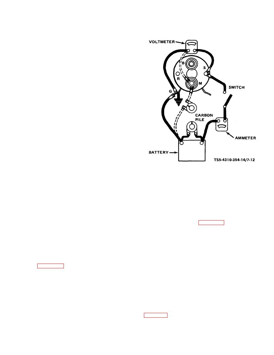
TS5-4310-354-14/7-12
grounded. If the commutator is worn,
dirty, out of round, or has high insulation,
Figure 7-12. Solenoid checking test setup.
the commutator should be turned down
and undercut.
To check the pull-in winding,
(2) Field Coils. Check the field coils for grounds
connect from the solenoid switch terminal(s),
and opens using a test lamp.
and to the solenoid motor (M) terminal.
(a) Grounds. Disconnect field coil ground
NOTE
connections. Connect one test prod to the
field frame and the other to the field
Connect the carbon pile between the
connector. If the test lamp lights, the field
battery and M terminal as shown in
coils are grounded and must be repaired
dashed lines on figure 7-12, instead
or replaced. (This check cannot be made
of across the battery, if needed, to
if the ground connection cannot be
reduce voltage to 5 volts for pull-in
disconnected.)
check.
If not needed, connect a
(b) Opens . Connect test lamp prods to ends
jumper directly from battery to the M
of field coils. If lamp does not light, the
terminal. At 5 volts, ampere reading
field coils are open.
should be 13-15.5 amps.
(3) Solenoid. Make a solenoid test setup as shown
CAUTION
in figure 7-12. Use a 12-volt battery and all
leads disconnected from solenoid. To check
To prevent overheating, do not leave
hold-in winding, make test connections to the
the pull-in winding energized more
solenoid switch (S) terminal and to ground (G).
than 15 seconds. The current draw
Use the carbon pile across the battery to
will decrease as the winding
decrease voltage to 10 volts. Observe ammeter
temperature increases.
reading. It should be 14.516.5 amperes. A high
reading indicates a shorted or grounded hold-in
f. Reassembly. Reassemble the starting motor
winding. A low reading indicates excessive
assembly in the reverse numerical sequence shown in
7-12


