TM 5-4310-354-14
c. Reassembly and Installation.
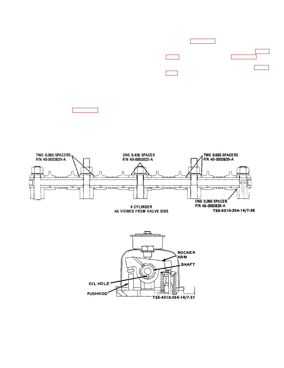
Install the spacers (13, 14) on the shaft as
indicated in figure 7-36. Make certain that the oil
holes in the shaft face downward and toward the
CAUTION
camshaft side of the engine, as shown in figure
The rocker arms are lubricated by
only one oil hole which must be assembled
means of oil forced through a hollow
downward. Install the retaining rings (9, figure
cylinder head stud into the rocker
arm shaft (18).
Oil is forced out
Install adjusting screws (16) in rocker arms (11).
through small holes in the rocker
arms (11), over the valve (40, 41)
(2) Before installing the rocker arm as sembly on the
stems and pushrods (19). For proper
cylinder head, check that rocker arms are
lubrication it is imperative that the
properly installed and that they move freely on
rocker arm and shaft be correctly
the shaft.
assembled and installed on the
engine. Refer to figure 7-35 and the
(3) Install the rocker arm assembly over the cylinder
following paragraphs.
head stud extensions and seat it firmly on the
(1) Coat the rocker arm shaft (18) lightly with clean
cylinder head. Make certain the rocker arm
lubricating oil. Slide the shaft supports (15, 10),
adjusting screws (16) are positioned over the
rocker arms (11), spacing springs (12), and
pushrods. Secure the rocker arm assembly to
spacers (13, 14) onto the rocker arm shaft (18).
the cylinder head with nuts (7) and washers (8).
TS 5-4310-354-14/7-36
Figure 7-36. Rocker arm, spacer locations.
TS 5-4310-354-14/7-37
Figure 7-37. Rocker arm shaft, oil hole position.
7-40


