TM 5-4310-354-14
2. On all piston rings that have the
groove cut on the inside
diameter of the ring, place the
undercut or groove towards the
top of the piston. See figure
(7) Inspect the crankshaft for any rough or
scored marks that might damage the
connecting rod bearing.
If any rough
marks are found, polish the shaft with an
oil stone, very fine emery cloth, or crocus
cloth. Clean the shaft thoroughly after
polishing.
NOTE
The cylinder number is stamped on
the connecting rods and caps on the
camshaft side and to the front of the
TS 5-4310-354-14/7-58
engine.
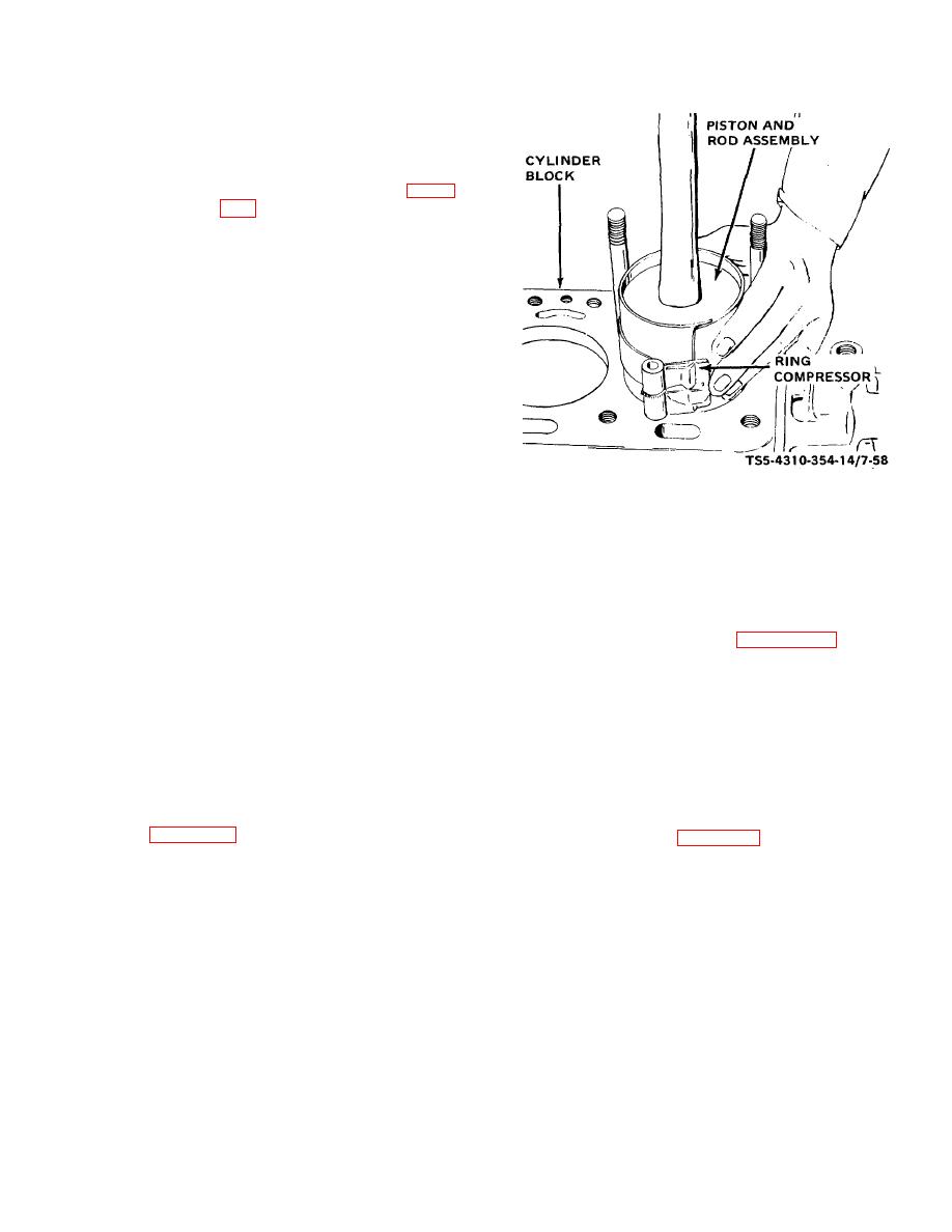
Figure 7-58. Piston installation.
(8) Select the proper piston and connecting
rod assembly for the first cylinder bore
(10) Install the bearings and connect the
and turn the crankshaft so that the
connecting rod to the crankshaft as
connecting rod journal for that cylinder is
follows:
in the lowered position. Apply a coat of
lubricating oil to the cylinder bores,
(a) With the piston entirely in the
pistons, rings, piston pin, and crankshaft
cylinder bore, insert the upper
journal.
bearing (4, figure 7-55) in the
connecting rod (11). Pull the piston
(9) Use a ring compressor to compress the
and rod assembly down until the
piston rings to facilitate installation of the
upper rod bearing (4) seats firmly on
piston and rod assemblies.
With the
the crankshaft journal.
connecting rod bearing cap and bearings
removed from the connecting rod, insert
(b) To check crankshaft journal-to-
the piston from the top of the cylinder
bearing shell clearance, place a
block. Use a hammer handle or block of
piece of plastic gauge material the
wood against the top of the piston to push
full width of the lower bearing (3)
the piston into the cylinder bore. See
about 1/4-inch (6.35 mm) off center
(see figure 7-59). Rotate the
rod is in line with the crankshaft journal
and will not score the journal.
7-63


