TM 5-4310-354-14
(4) Inspect the thrust plate (2) for worn or
scored thrust surfaces and distortion.
(5) Inspect the camshaft gear for worn,
cracked, or broken teeth, and worn
keyway. Replace a damaged gear.
(6) Check the valve tappets for wear and
replace any that exceed 0.005 inch (0.127
mm) clearance in the cylinder block bore.
c. Reassembly and Installation.
(1) Insert the valve tappets in their respective
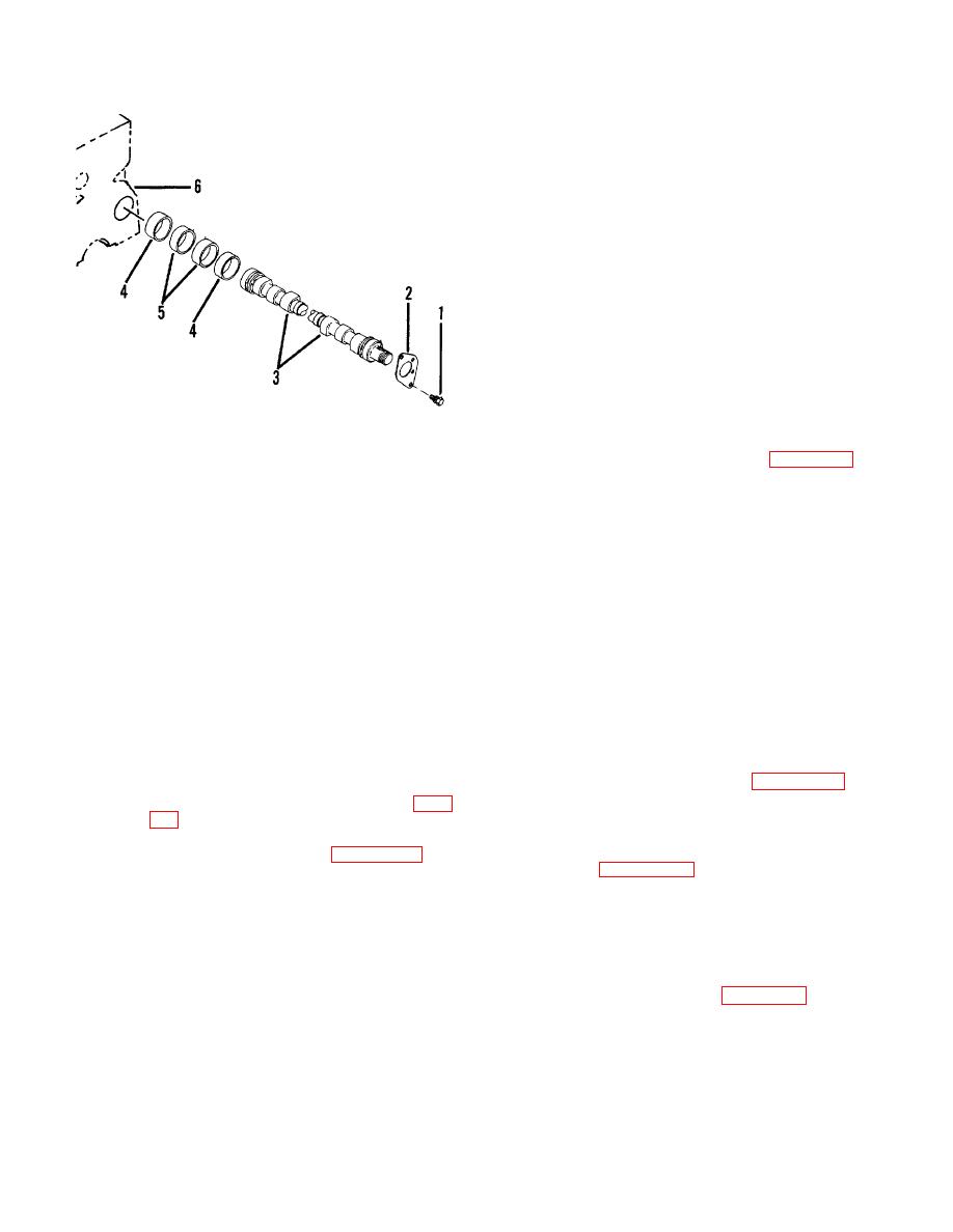
1.
Bolt and washer (2)
holes in the cylinder block. Make certain
2.
Thrust plate
that they are in the raised position in the
3.
Camshaft
block before installing the camshaft.
4.
Front and rear bearing (2)
5.
Intermediate bearing (2)
(2) Install the front, rear, and intermediate
TS 5-4310-354-14/7-53
6.
camshaft bearings (4, 5, figure 7-53) in the
cylinder block.
Replacement camshaft
Figure 7-53. Camshaft and bearings,
bearings are precision cut and no line
removal and installation.
reaming is required.
When installing,
make sure the oil holes in the bearings are
(9) If it is necessary to remove the camshaft
aligned with the oil holes in the drilled
gear from the camshaft, remove the nut,
passageways in the cylinder block. Tap
place the shaft in an arbor press and, with
bearings into place with a bearing driver.
suitable supports under the gear, press
the shaft out of the gear. Remove key
(3) If the camshaft gear was removed from
from camshaft and remove the camshaft
the camshaft (3), place the thrust plate (2)
thrust plate.
on the camshaft (3) and press the gear
onto the camshaft with key in place.
(10) After the camshaft has been removed
Secure with nut. Make certain all tappets
from the engine, the valve tappets can be
are in the raised position. Carefully insert
removed from the underside of the block,
the assembled camshaft into the cylinder
as necessary.
block, aligning the timing marks on the
camshaft gear with the timing marks on
b. Cleaning, Inspection, and Repair.
the crankshaft gear (figure 7-50). This
ensures correct timing of the valves.
(1) Clean all parts in accordance with para
5-7.f.
(4) Secure the thrust plate to the cylinder
block with two bolt and washer assemblies
(2) Inspect the camshaft (3, figure 7-53) for
scored or worn cams and bearing
surfaces, damaged oil pump gear, threads
play. Normal end play is 0.005 to 0.008
or keyway, or worn thrust surfaces.
inch (0.127 to 0.203 mm) and shall not
Replace camshaft (3) if it has scuffed,
exceed 0.012 inch (0.3048 mm).
To
scored, or cracked valve cams. Replace
decrease end play, use a draw file to
camshaft if any bearing journal diameter is
remove a small amount of metal from the
worn to less than 2.051 inches (52.0954
camshaft gear hub on which the thrust
mm).
plate rides. See figure 7-54. To increase
end play, add a shim between the
(3) Inspect the bearings (4, 5) for scored or
camshaft gear hub and the camshaft
worn bores, cracks, or scored faces.
bearing, or, using a piece of very fine
Replace worn or damaged bearings. The
emery cloth on a surface plate, polish the
maximum allowable clearance between
thrust plate to the desired thickness.
camshaft journal and bearing bore is
Check the backlash of the camshaft gear
0.006 inch (0.1524 mm).
to the crankshaft gear.
7-59


