TM 5-4310-354-14
Section X. CAMSHAFT AND CAMSHAFT BEARINGS
7-21. General. The camshaft is supported on large
diameter, pressure-lubricated, removable bearings in the
crankcase. The camshaft is driven by the camshaft gear
which meshes with the crankshaft gear. The crankshaft
gear and camshaft gear each have timing marks for
proper assembly of the camshaft to produce the proper
firing order and operation of the rocker arm assembly.
The camshaft operates the rocker arms in the proper
order via the valve tappets and pushrods. A toothed
portion of the camshaft, located near the center of the
camshaft, engages with and drives the oil pump gear.
7-22. Camshaft and Camshaft Bearings.
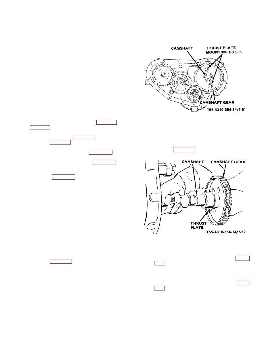
TS 5-4310-354-14/7-51
a. Removal and Disassembly.
Figure 7-51. Thrust plate mounting bolts, removal and
(1) Remove the engine from the unit (para 5-12 and
Installation.
(7) Remove the thrust plate mounting bolt and
(2) Remove the oil pan (para 7-15) and oil pump
washer assembly and pull the camshaft
assembly (para 7-16).
assembly forward out of the cylinder block as
shown in figure 7-52.
(3) Remove the fan and drive belt (figure 7-33).
(4) Remove the gear housing cover (figure 7-49).
(5) Remove the cylinder head cover and rocker arm
assembly (para 7-12). Remove the pushrods
from cylinder block.
CAUTION
It is necessary for removal of the
camshaft that the valve tappets be in
the raised position. To accomplish
this, set the engine on the
bellhousing or upside down (support
the engine on suitable blocks so that
TS 5-4310-354-14/7-52
cylinder head studs clear), and push
the tappets to raised position.
Figure 7-52. Camshaft and thrust plate, removal and
(6) With the tappets in the raised position, rotate the
Installation.
engine crankshaft until the two holes in the
camshaft gear expose the thrust plate mounting
(8) Remove the camshaft bearings (4, 5, figure
bolts; see figure 7-51.
hand, drive out the camshaft bearings (4, 5) with
a brass drift. If difficulties are encountered
removing the rear camshaft bearing, it may be
necessary to remove the bellhousing (para
7-58


