TM 5-4310-360-14
6-2. Pistons, Rings, Connecting Rods, Cylinder
Block, Crankshaft and Crankcase - continued.
1.
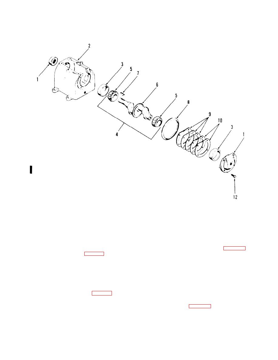
Oil seal
2.
Crankcase
Bearing cup
3.
4.
Crankshaft assembly
5.
Bearing cone (2)
6.
Crankshaft
7.
Key, Woodruff
8.
Oil feeler ring
9.
End cover gasket (3)
10.
End cover gasket (2)
11.
End cover
12.
Screw, cap, hex head (4)
Figure 6-2. Crankshaft and crankcase.
Reassembly and Installation.
c.
(3)
Measure the clearance between small
end of connecting rod and wrist pin.
Crankshaft crankcase. Before assem
(1)
Also measure the clearance between
bling, the crankshaft (6, figure 6-2)
large end of connecting rod and crank-
must be fitted to the crankcase (2).
shaft. Refer to table 1-1 for allowable
Install cover (11), gaskets (9 and 10)
clearances.
and secure with end cover screws (12)
evenly. End cover gaskets (9 and 10)
serve as shims and are furnished in
(41
Examine crankshaft and pistons for
two thicknesses. The proper combina-
wear, scuffing, scoring, etc., and
tion must be selected so crankshaft (6)
replace parts damaged. If parts exceed
can be spun in the bearings without
clearance listed in table 1-1, replace
end play. Refer to table 1-2 for end
them.
play allowance. Also see that oil feed
ring (8, figure 6-2) rotates freely on
the crankcase. Remove crankshaft
from the crankcase anti hold long end
(5)
inspect tapered roller bearing for
in a vise using soft jaws to prevent
rough, pitted, or scored surfaces
damage.
Replace a defective bearing.
6-3
Change 1


