TM 5-4310-451-14
5-36. PISTON REPAIR (Con’t).
8.
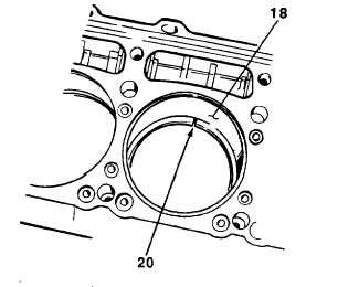
Check compression piston ring gaps as follows:
(a)
Place three new compression piston rings
into cylinder sleeve (18), one at a time, to
depth of 2-3 in. (5.08-7.62 cm). Piston
skirt may be used to position compression
piston rings parallel to top of cylinder
sleeve.
(b)
Measure compression piston ring gaps
(20) with feeler gage. Compression piston
ring gaps should be less than 0.0600 in.
(1.5240 mm).
(c)
Repeat step a for four new oil rings.
(d)
Measure oil ring gaps with feeler gage.
Maximum oil ring gap should be 0.0430 in.
(1.0922 mm).
9.
Check compression piston ring side clearance as follows:
(a)
Measure compression piston ring side clearances with feeler gage. Top compression piston ring maxi-
mum side clearance should be 0.0100 in. (0.2540 mm). No. 2 compression piston ring maximum side
clearance should be 0.0220 in. (0.5588 mm). No. 3 compression piston ring maximum side clearance
should be 0.0150 in. (0.3810 mm).
(b)
Measure oil ring side clearances with feeler gage. Oil ring maximum side clearance should be 0.0080 in.
(0.2032 mm) for each of four oil rings.
c.
ASSEMBLY
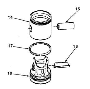
1.
Place piston (10), top down, on work surface.
Install sleeve bearing (16) to piston.
2.
Apply coat of lubricating oil to spacer ring (17).
3.
Install spacer ring (17), bevel side up, to piston
(10). Ensure that spacer ring rotates freely on
piston with no sticking or binding.
4.
While compressing spacer ring (17), install
piston skirt (14) to piston (10). Ensure that
piston skirt rotates freely on piston with no
binding.
5.
Apply coat of lubricating oil to piston pin (15).
6.
Install piston pin (15) through piston skirt (14)
and piston (10) with threaded holes facing upward.
TA74993
5-113