
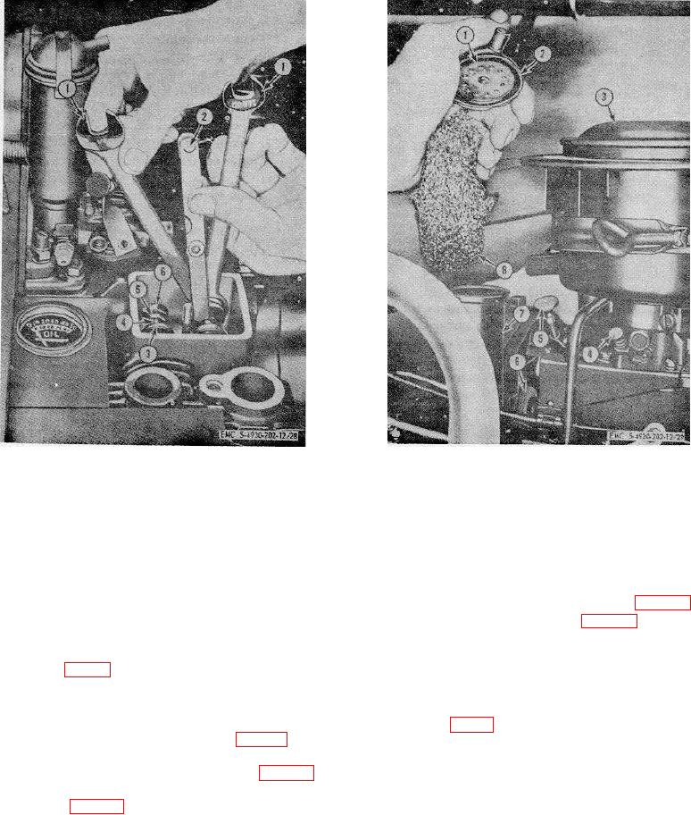
1
Wrench, 1/2 in.- 9/16 in. (2 rqr)
1
Crankcase breather valve
2
Feeler gage
2
Crankcase breather cap
3
Valve spring and roto cap
3
Carburetor air cleaner
4
Valve stem
4
Carburetor adjusting screw
5
Adjusting screw
5
Fuel pump primer lever
6
Tappet
6
Governor adjusting nut
7
Crankcase breather tube
Figure 28. Valve adjustment.
8
Crankcase breather tube baffle
Figure 29. Servicing crankcase breathes.
means of the adjusting screw (5) in the
(5) Connect the governor linkage (par. 112).
end of the tappet (6). The screw is self-
locking and will maintain the setting.
(6) Install the carburetor (par. 110).
(3) Adjust the valves of the right-hand
cylinder, by rotating the blower wheel (1,
125. Crankcase Breather Assembly
fig. 31) one full revolution and repeating
a. Removal.
the adjustment procedure.
(1) Remove the short piece of tube,
c. Installation.
connecting the crankcase breather cap (2,
(1) Install new valve cover gaskets.
fig. 29) to the air cleaner (3).
(2) Install valve covers (11, fig. 21) and
(2) Pull the crankcase breather assembly up
secure with nuts (12) and lockwashers.
and out of the cylinder block.
(3) Install the manifold and muffler (par. 123).
(3) Remove the spring clip which secures the
(4) Connect the fuel lines to the fuel pump
crankcase breather cap (2) and valve (1)
to the crankcase breather tube (7), and
remove the cap.
67