d. Inspection.
(1) Perform a thorough general inspec-
tion of all parts of the compressor assembly,
checking particularly for cracked and chipped
casting, damaged screw threads, and finished
surfaces t h a t a r e scored, p i t t e d , or
scratched.
(2) Inspect connecting tube assemblies
and fittings for worn or damaged screw
threads, cracks, dents, sharp bends, and other
defects. Pay particular attention to the flare
ends of the tubes since cracking is most apt to
occur at the root of the flare. Do not attempt
to reclaim a connecting tube assembly by re-
placing component parts.
(3) Inspect cylinder bores, pistons, con-
necting rods, and pins for excessive wear,
scoring, and other indications of damage. Dis-
card all damaged and excessively worn parts.
(4) Inspect valves, valve seats, valve
springs, and stops for nicks, scoring, burning,
warping, and noticeable wear. Discard all worn
or damaged parts.
(5) Replace all gaskets.
e. Repair. The repair of component parts or
subassemblies of the compressor assembly
should not be attempted. Discard all damaged,
worn, and questionable parts and install new
items during reassembly of the equipment.
f.
Reassembly. Reassemble the compressor
in reverse of numerical sequence as illustrated
in figures 7-1 through 7-3.
sembly as instructed in paragraph 3-97.
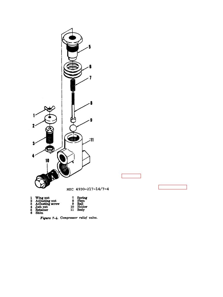
Section II. COMPRESSOR RELIEF VALVE
the pressure reaches the high limit thereby un-
7-3. General
loading the compressor. When the receiver
The compressor relief value is a pressure
pressure drops to the low limit, the valve re-
regulated device which transmits receiver
leases pressure from the suction valve un-
pressure to the suction valve unloaders when


