
setting put the cover on the regulator and connect the regulator as in figure 86. Reduce the generator speed
until the contact points close, then bring up the speed until the contacts open at the voltage setting.
(3) Current regulator. Connect the regulator to the batteries and generator. Bridge the voltage regulator
contacts (fig. 89), and insert an ammeter in the BATTERY line. Operate the generator at medium speed and
note the current regulator setting. The contacts should open at 10 amperes. If the contacts do not open at
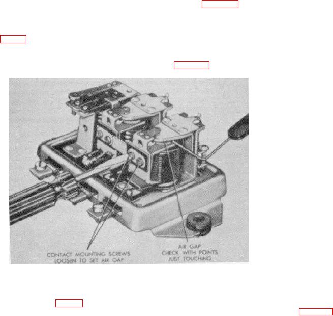
the specified current, disconnect the regulator. Measure the air gap between the armature and the center of
the core with the contacts closed. Refer to the center unit in figure 87, and adjust the contacts the same as
Figure 87. Adjusting voltage regulator air gap.
for the voltage regulator discussed in (2) above. The air gap should be 0.075-inch. Turn the adjusting
screw of the center unit (fig. 88) in to increase the current setting, and out to decrease the current setting.
After each change of current setting put the cover on the regulator and connect the regulator as in figure 89.
194