crankshaft gears coincide. Turn the engine over if necessary. Release the valve tappets (16, fig. 106) and install the
cylinder head and valves (par. 122e). Install the fuel pump (par. 75b). Install the gear cover (par. 220c). Install the
crankcase covers (par. 216c).
225. Crankcase and Cylinder Sleeves
a. Removal (fig. 106). Remove the engine-compressor from the frame (par. 214). Remove both cylinder heads
(pars. 122a and 126a), crankcase covers (par. 216a), rear support (par. 221a), gear cover (par. 220(a), crankshaft and
main bearings
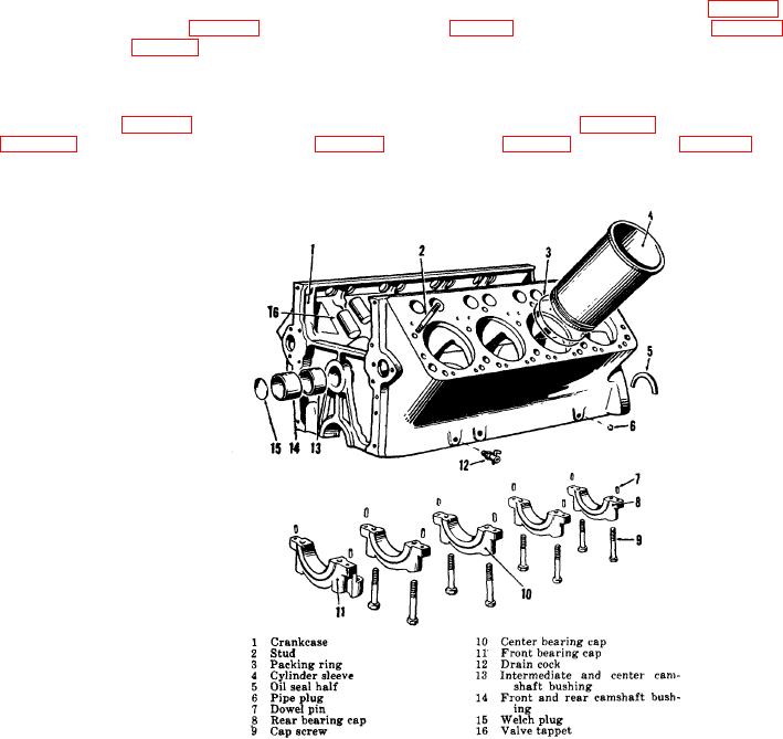
Figure 106. Exploded view of crankcase and sleeves.
240

