TM9-4310-396-13
a. Test Engine Generator. - continued
(2)
Engine generator stator coil continuity test. - continued
(f)
Remove wire (5, Figure 5-8) from clamp (6).
(g)
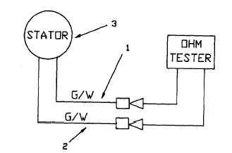
Disconnect green/white wire (1 and 2, Figure 5-6). Check engine generator stator (3) for continuity
using a circuit tester. If continuity is not detected (W), replace stator coil (3). Refer to Table 5-4.
Figure 5-64. Stator Continuity Diagram.
Table 5-4 Continuity Test
Tester's Reading
Continuity
Evaluation
Comments
W
NO
Normal
---
0W
YES
Abnormal
Replace the stator coil
(3)
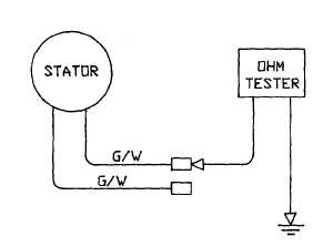
Engine generator stator ground test.
(a)
Connect one ohmmeter wire to one green/white wire stator lead. Connect other ohmmeter wire to
engine block.
(b)
When continuity is detected, replace stator.
Figure 5-7. Stator Ground Test Diagram.
5-13