TM 5-4310-354-14
TS 5-4310-354-14/7-44
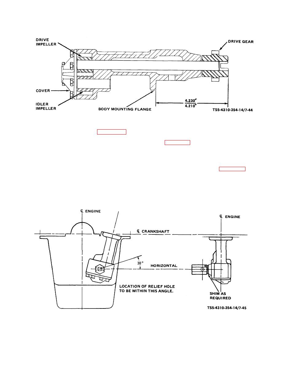
Figure 7-44. Oil pump drive gear, installation.
(3) Install the idler shaft (15, figure 7-43), if
on the pump, must be turned so that the relief
removed, and install the idler impeller (14).
hole is aligned within 30 of horizontal (see
(4) Install the cover (11) and secure with cap
spraying up into the cylinder bore, and will direct
screws (8), lock washers (9), and screw
the spray toward the center of the engine and
assemblies (10).
Tighten progressively and
against the oil pan surface. If the oil pressure
evenly.
regulator is in an incorrect position when
tightened, add shims (5, figure 7-43) until the
(5) Install the oil pump strainer (6) on the pump
proper alignment is achieved.
impeller cover (11) by turning in clockwise. Do
not apply force against the screen.
d. Testing. Bench test the oil pump assembly on a
suitable test fixture that is capable of turning the drive
(6) Install the oil pressure regulator (3) with a new
gear at 250 rpm. The setup should have an oil
lock washer (4). The regulator, when mounted
TS 5-4310-354-14/7-45
Figure 7-45. Oil Pressure regulator, installation.
7-50


