TM 5-4310-354-14
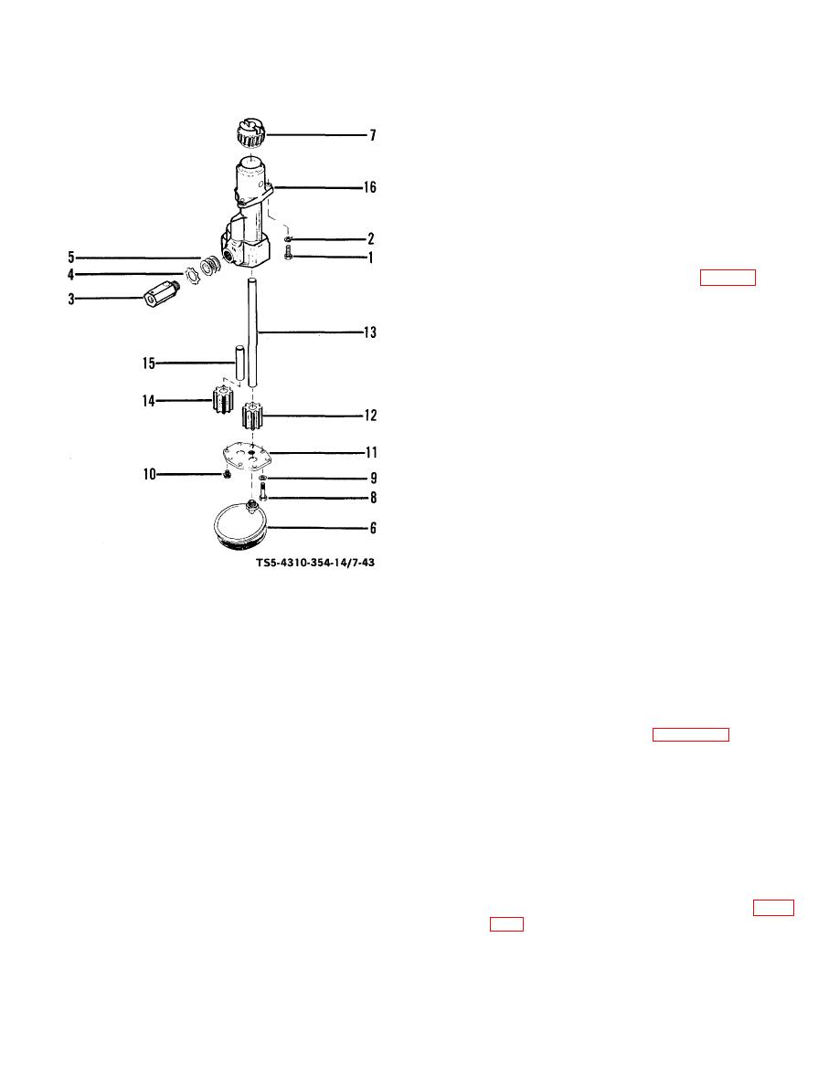
(c) Remove drive impeller (12) and shaft (13)
as an assembly.
If necessary, press
impeller (12) off shaft (13).
(d) Remove impeller (14) from shaft (15).
Shaft (15) is a press fit into body (16).
Pull the shaft (15) from body (16) only
when necessary.
b. Cleaning, Inspection, and Repair.
(1) Clean all parts in accordance with para 5-7. f.
(2) Inspect the oil pump strainer (6) for clogged
screen, holes, damaged threads, dents, or other
damage. Make sure the oil passage is clear and
unobstructed. Replace a damaged or distorted
strainer.
(3) Inspect all gears (7, 12, 14) for worn or broken
teeth; replace if damaged.
(4) Inspect all parts for burrs, pitting, rust, scoring,
cracks, breaks, and damaged threads. Replace
any damaged parts.
(5) Replace idler shaft (15) if shaft has turned in
pump body (16) or is worn smaller than 0.6220
inch (15.7988 mm) diameter at gear bearing
area.
TS 5-4310-354-14/7-29
(6) Replace drive shaft (13) if shaft has turned in
1.
Cap screw (2)
9.
Lock washer (2)
gears or is worn smaller than 0.6220 inch
2.
Lock washer (2)
10.
Screw assy (6)
(15.7988 mm) diameter at bearing points.
3.
Regulator
11.
Cover
4.
Lock washer
12.
Drive impeller
(7) Check piston for binding in regulator body;
5.
Shims (AR)
13.
Drive shaft
replace regulator (3) if piston binds.
6.
Strainer
14.
Idler impeller
7.
Drive gear
15.
Idler shaft
c. Reassembly.
8.
Cap screw (2)
16.
Pump body
(1) Press drive impeller (12, figure 7-43) onto the
Figure 7-43. Oil pump assembly, disassembly and
drive shaft (13) so that the outside face of the
reassembly.
impeller and the end of the shaft are flush.
Once removed, do not press old parts back
(a) Remove the strainer (6) from cover (11).
together.
Bend up tangs of lock washer (4) and
remove regulator (3), lock washer (4), and
(2) Insert the shaft and impeller a sembly into the
s
shims (5). Do not disassemble regulator
pump body (16). Press the drive gear (7) onto
(3).
the shaft (12).
Replace gear that can be
pressed onto the shaft with less than 35 pounds
(b) Use a gear puller to remove drive gear (7)
(15.876 kg) gauge pressure. Press the gear
from shaft (13). Remove the two cap
onto the shaft to the dimensions shown in figure
screws (8) and lock washers (9), six screw
assemblies (10). and cover (11).
7-49


