TM 5-4310-354-14
1.
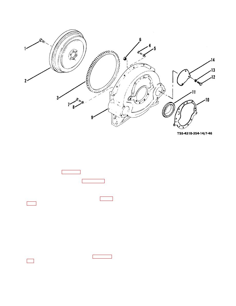
Flywheel cap screw (6)
8.
Washer (4)
2.
Flywheel
9.
Bellhousing
3.
Ring gear
10.
Gasket
4.
Cap screw (6)
11.
Seal
5.
Lock washer (8)
12.
Cap screw (3)
6.
Nut (2)
13.
Lock washer (3)
TS 5-4310-354-14/7-46
7.
Cap screw (4)
14.
Cover
Figure 7-46. Flywheel and bellhousing, disassembly and reassembly.
(4) Do not attempt to remove ring gear (3) from
(2) Inspect the flywheel ring gear (3) for brok en or
flywheel (2) unless it is damaged and must be
cracked teeth.
If damage is evident and
replaced.
replacement is necessary, drive the gear (3)
from flywheel (2) with a blunt chisel.
(5) Remove the oil pan (para 7-15).
(3) Inspect the flywheel (2) for distortion, cracks, or
(6) Remove rear oil pan adapter (figure 7-41) by
other damage or wear. Replace a damaged
first removing two nuts and lock washers
flywheel.
securing adapter to cylinder block studs; then,
remove four cap screws and lock washers
(4) To install a new ring gear (3), heat it in an oven
securing adapter to the bellhousing (9, figure
or with a heating torch to approximately 600F
(315.6C). Do not overheat. Place heated ring
gear on flywheel (2) and quickly drive onto
(7) Remove cap screws (4, 7), washers (5, 8) and
flywheel until gear is firmly seated.
nuts (6). Separate bellhousing (9) from cylinder
block and remove gasket (10).
(5) Discard and replace gasket (10) and oil seal
(11). Make sure all gasket material is removed
(8) Press seal (11) out of bellhousing (9). Remove
from mating surfaces.
cap screws (12), lock washers (13), and cover
(14) from bellhousing (9).
(6) Inspect the bellhousing (9) for cracks, distortion,
and other damage; replace a damaged
b. Cleaning, Inspection, and Repair.
bellhousing.
(1) Clean all parts in accordance with paragraph
(7) Check that bellhousing dowel pins in the block
5-7.f.
are tight and in good condition.
7-52


