TM 5-4310-354-14
c. Reassembly and Installation.
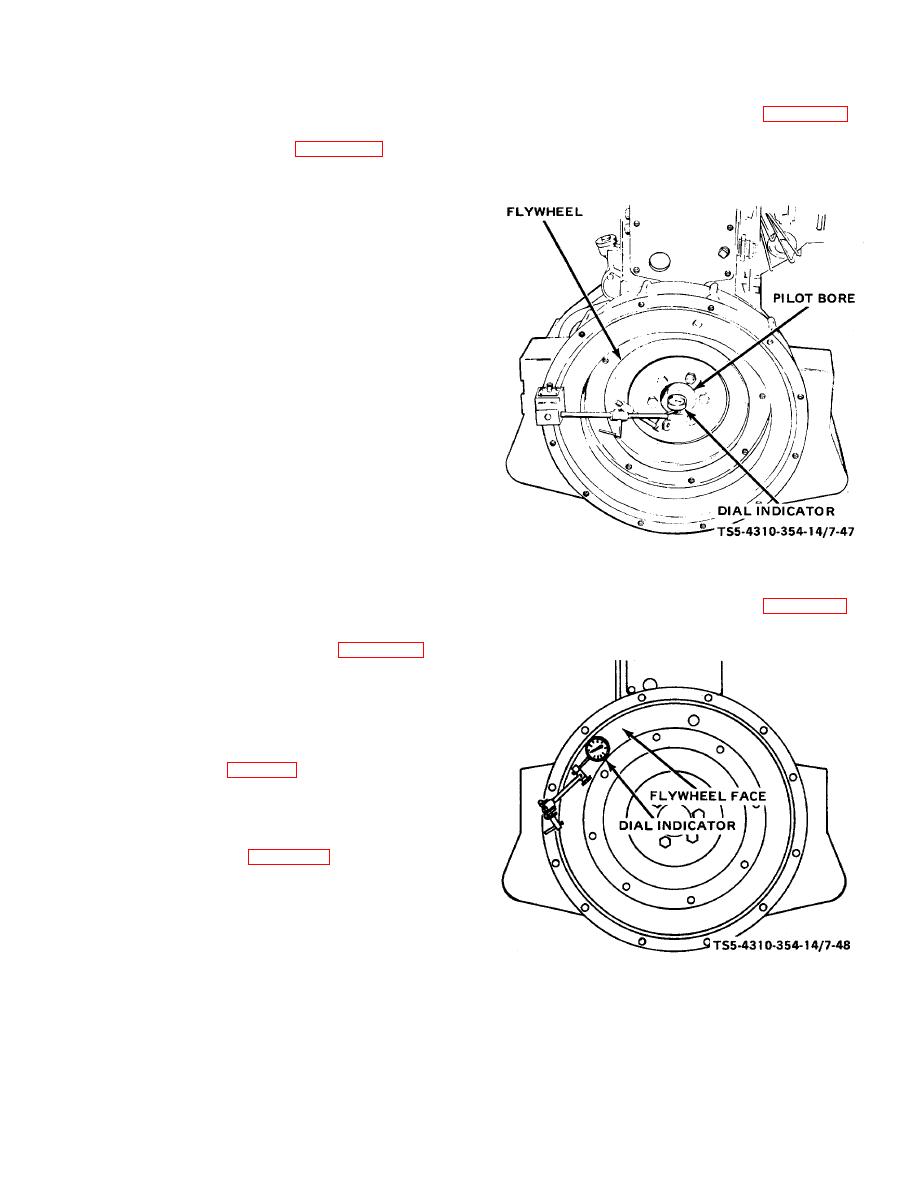
(8) Attach an indicator, as shown in figure 7-47, to
check the concentricity of the pilot bore. This
(1) Install a new oil seal (11, figure 7-46) in the
should not exceed 0.005 inch (0.127 mm) total
bellhousing (9), using a small amount of sealing
indicator reading.
compound in the bore before pressing in the
seal.
If new seal is pre-coated, sealing
compound is not required.
Cement a new
gasket (10) to the bellhousing (9), allowing the
cement to dry sufficiently to prevent the gasket
from slipping at installation.
(2) Clean and polish the oil seal surface of the
crankshaft to remove nicks or scratches. Use
crocus cloth or very fine polishing cloth.
(3) Apply a thin coat of oil soap to the seal and the
seal surface of the crankshaft. If seal is already
oil treated, additional lubricant is not required;
however, take care to keep the seal surface
clean during reassembly. Make sure that the
top rear cam thrust plate attaching screw hole is
plugged with a setscrew. This hole runs into an
oil hole in the block.
Carefully place the
bellhousing (9) on the cylinder block so that the
seal is not damaged as it engages the
TS 5-4310-354-14/7-47
crankshaft. Align so that the dowels properly
enter their respective holes.
Seat the
Figure 7-47. Indicating flywheel pilot bore.
bellhousing (9) to the engine and install the cap
screws (4, 7), nuts (6), and lock washers (5, 8)
(9) Attach the indicator, as shown in figure 7-48, to
but do not tighten.
check the face of the flywheel. Runout
(4) Install the rear oil pan adapter (figure 7-41),
securing it to the cylinder block with two nuts
and lock washers. Secure the adapter to the
bellhousing with four bolts and lock washers.
Tighten down the bellhousing cap screws and
nuts evenly and securely.
(5) Install the oil pan (para 7-15).
(6) Turn the crankshaft so that the timing cylinder
(No. 1) is in the top dead center position.
(7) Turn the flywheel (2, figure 7-46) so that the DC
timing mark is in line with the timing hole in the
bellhousing (9). Install the flywheel (2) on the
crankshaft. Note that one of the six cap screws
(1) is off center so that the flywheel (2) can only
be installed in one position. This ensures proper
TS 5-4310-354-14/7-48
location of the flywheel on the crankshaft for
timing purposes. Draw the flywheel onto the
Figure 7-48. Indicating flywheel face.
crankshaft by tightening the six cap screws
alternately and evenly. Torque the bolts to 80
foot-pounds (11.064 kg-m).
7-53


