TM 9-4310-397-14
(i)
Adjust valves per the following:
NOTE
The valve clearance can be adjusted with the engine cold or hot.
1
Using engine rotation tool (item 15, section III, appendix B), rotate engine flywheel in running direction
(clockwise viewed from water pump) until No.1 piston (front) has reached top dead center (TDC) on
compression stroke. Insert timing pin (item 16, section III, appendix B) into flywheel.
NOTE
When No.1 piston is at TDC on compression stroke, valve springs of No.1 cylinder are not
under tension.
2
Adjust intake valve clearance to 0.014 in. (0.35 mm).
3
Adjust the exhaust valve to 0.018 in. (0.45 mm).
NOTE
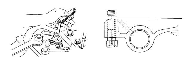
Some engines may have rocker arms with socket head hollow set screw located above the
adjusting screw. The set screw must be backed off two or three turns before making valve
adjustment.
4
Torque set screw to 7 ft-lb (10 Nm) after adjustment is made. Make sure set screw does not restrict lube
oil passages in rocker arm.
Figure 6-31. Valve Adjustment
6-31

