TM 9-4310-397-14
6-6. ROCKER ARMS, CYLINDER HEAD, AND VALVES REPLACEMENT. - Continued
(b)
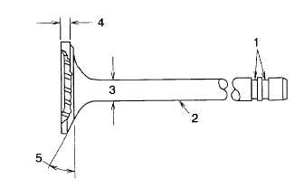
Inspect grooves (Figure 6-27, 1) on valve stem for damage. Also inspect stems (2) for signs of scuffing, which
may indicate insufficient valve guide-to-valve stem clearance. Replace if defects are evident.
Figure 6-27. Valve Inspection
(c)
Use Valve Inspection Center (item 14, section III, appendix B) to determine if valves are bent or have excessive
runout. Maximum permissible runout of valve face is 0.002 in. (0.05 mm).
1
Measure valve stem OD (3) and margin (4).
2
Valve stem OD should be 0.3715 + 0.005 in. (9.445 + 0.015 mm).
3
Valves determined to be serviceable should be refaced to specified angle (5).
4
Engine intake valve and exhaust valve should both be 43.5.
(12)
Using a telescopic gauge, check valve guides for wear per the following:
(a)
ID of valve guide bore in a new cylinder head should be 0.374-0.375 in. (9.51-9.53 mm).
(b)
New guide-to-valve stem clearance should be 0.002-0.004 in. (0.05-0.10 mm).
(c)
Maximum permissible clearance should be 0.006 in. (0.015 mm).
(13)
Inspect the valve seats for cracks, pits, and erosion.
d. Repair. Repair is limited to replacement of defective, damaged, or out-of-tolerance parts.
e. Installation.
(1)
Install valves per the following:
(a)
Apply Valve Stem Lubricant (item 14, section II, appendix E) to valve stems and guides.
NOTE
Valves must move freely and seat properly in head.
(b)
Insert valves in head (must go in same location as when removed).
(c)
Position valve springs. End of spring must be in machined counterbore of head.
6-28