FIELD AND DEPOT MAINTENANCE INSTRUCTION
Section I. OVERHAUL AND REPLACEMENT STANDARDS
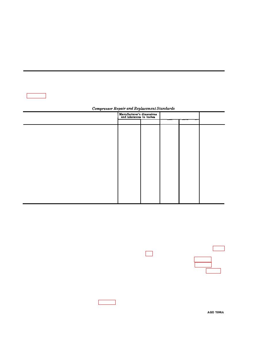
and clearance for the air compressor.
Maximum
Desired clearance
allowable wear
and clearance
Min.
Max.
Min.
Max.
Cylinders
Bore,
low-pressure
-----------------------------------------
------
3.2495
0.004
------
3.2505
Bore,
High-pressure
---------------------------------------
------
------
1.7505
1.7495
0.002
------
------
------
Out-of-round
------------------------------------------------
0.001
------
Taper
------
------
0.001
------
------
-------------------------------------------------
Crankshaft
1.376
Journal
(rod)
size
------------------------------------------
1.375
Taper
----------------------------------------------------------
------
______
------
0.001
------
Out-of-round
------------------------------------------------
------
------
------
------
0.0005
End
play
-----------------------------------------------------
0.000
------
------
0.002
and
Pins
Piston,
Low-pressure
-------------------------------------
0.005
0.003
3.2465
3.2455
0.005
Piston,
High-pressure
------------------------------------
0.0035
0.0015
1.748
1.747
0.003
Pin,
low-pressure
-------------------------------------------
0.0005
0.0001
0.9377
0.9375
Pin,
high-pressure
----------------------------------------
0.0005
0.0001
0.7505
0.750
Connecting
Rod
Bearing,
id
--------------------------------------------------
0.007
0.0001
1.357
1.353
Bearing,
side
clearance
----------------------------------
------
0.010
------
0.017
No special tools are needed to perform field and depot maintenance on these air compressors.
No special equipment is needed to perform the field and depot maintenance on these air compressors.
Section Il. AIR COMPRESSOR ASSEMBLY
(2) Disconnect the intercooler and the
109. General
aftercooler from the manifolds (pars.
The compressor assembly on Model OEH-
34-60-ENG-1 and Model LP-512-ENG is a
(3) Remove the side plates (par. 98).
two-stage, two-cylinder, air cooled unit. There
(4) Remove the air cleaner (par. 85).
is one low-and one high-pressure piston operat-
(5) Revolve the crankshaft (13, fig. 24)
ing off the crankshaft. The crankshafts sup-
until the connecting rod nuts (8) are
ported at either end by ball bearings.
accessible through the side of the com-
pressor crankcase.
Rods and Cylinder Block
(6) Remove the 4 nuts (8) lockwashers
a. Removal and Disassembly.
(7) 1 oil scoop (11),2 lower half bear-
(1) Remove the tube assemblies (par. 97).
ings (10), and the 4 brass shims (5)


