
the lower half sleeve bearing caps (6
the piston with the retaining rings
and 12) and oil scoop with lockwashers
(21).
(7) and hex nuts (8). Tighten the
(4)
Position the low-pressure piston (28)
nuts to 25 foot-pounds torque.
on the connecting rod (14) and start
(14)
If the connecting rod is loose, remove
the piston pin (29) in the piston.
a shim and reassemble the cap to the
Drive the pin through the bushing in
rod. Repeat the process until a 0.002-
the connecting rod and lock the pin in
inch clearance is obtained between
the piston with the retaining rings,
the sleeve bearings in the connecting
(30).
rods.
(5)
Expand the piston rings sufficiently to
(15)
Install the air cleaner (par. 85).
allow the rings to slide freely over
the piston to the proper position.
Install the side plates (par. 98).
(16)
(6)
Install piston rings (26, 27, 24, and
Install the aftercooler (par. 90) and
(17)
the intercooler in the manifolds (pars.
25) in their proper groove on the low-
and high-pressure pistons (28 and 23),
starting with the bottom ring until
Install the tube assemblies (par. 87).
(18)
all rings are replaced in order. Space
ring gaps so that they are not lined
up.
(7)
Lubricate each piston and connecting
rod assembly with a light coat of en-
gine oil. Compress the piston rings
on each piston and slide the assembled
pistons and connecting rods in the
proper bore of the cylinder block. In-
stall the connecting rod bolts (15 and
19) in the connecting rods (14 and 18)
(8)
Install the six studs (6, fig. 19) in the
crankcase (1, fig. 24).
(9)
Position a new cylinder flange gasket
on the studs in the crankcase and in-
stall the cylinder block in place on the
crankcase. Secure with the 6 nuts
(5, fig. 19). Tighten to 45 foot-pounds
(10)
Install the upper half sleeve bearings
(13 and 17, fig. 25) in the high-and
low-pressure connecting rods (14 and
18). Pull the rods and bearings down
on the crankshaft and install the
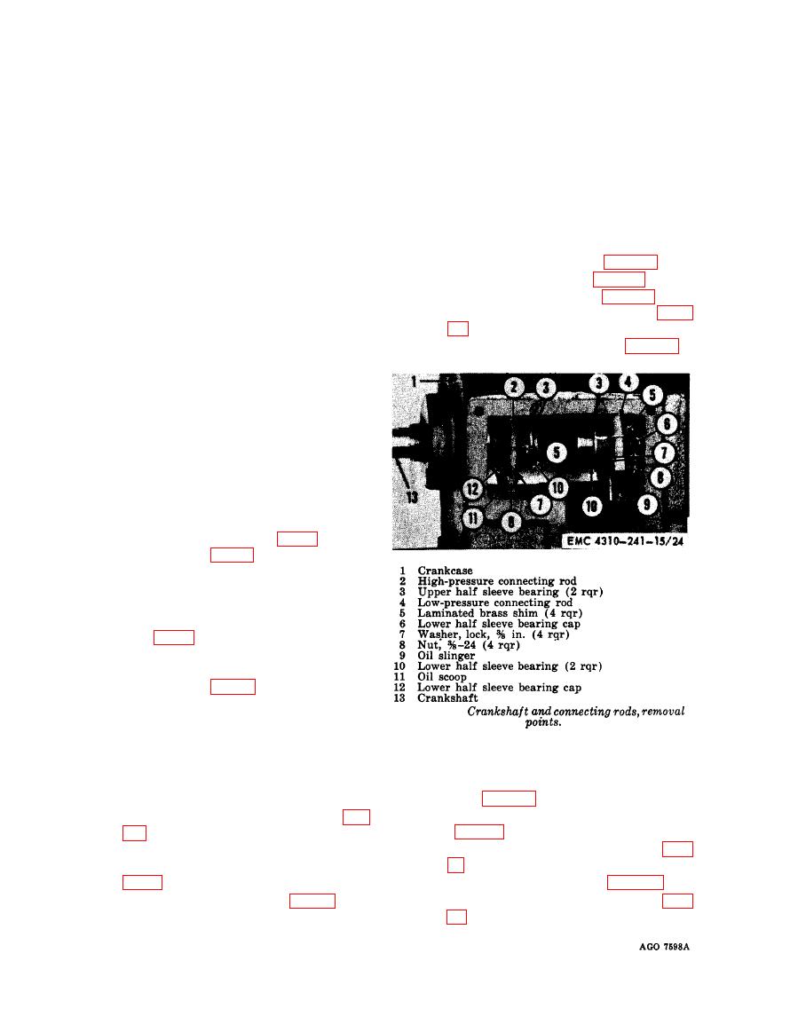
111. Crankshaft
shims (6) on the bolts (15 and 19).
a. Removal.
(11)
Install the oil slinger (7) in the bear-
(1) Remove the release valve unloader
ing cap of (6) of the low-pressure pis-
tube (par. 87).
ton connecting rod.
(2) Remove the crankcase breather tube
(12)
Position the sleeve bearings (10, fig.
(3) Remove the unloader assembly (par.
caps (6 and 22) and install the caps
92) .
on the connecting rod bolts (15 and 19,
(4) Remove the side plates (par. 98).
fig. 25) .
(13)
Install the oil scoop (11, fig. 24) on
(5) Remove the crankshaft flywheel (par.
the high-pressure piston and secure
