TM 5-4310-354-14
(4) Install the oil pan (para 7-15. c, as applicable).
(8) Install the fuel injection pump (figure 7-15),
assembling the pump gear (24, figure 7-49),
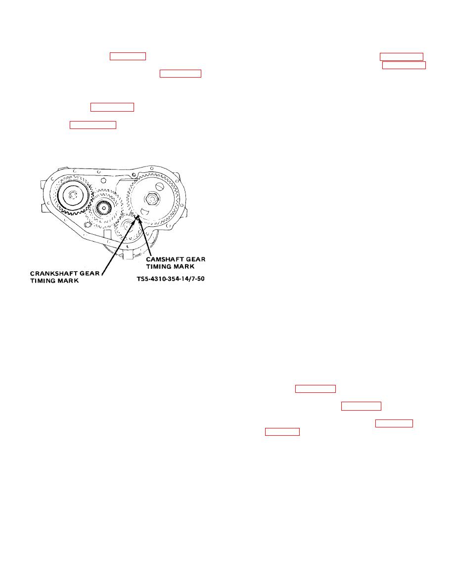
(5) Install camshaft gear key (21, figure 7-49) in,
washer (23), and nut (22) on pump shaft.
keyway on camshaft. Install camshaft gear (20)
on camshaft with timing mark on the camshaft
(9) Use a small amount of sealing compound in the
gear aligned with crankshaft gear timing mark as
seal (18) bore of the gear housing cover (12)
shown in figure 7-50.
Insert a brass bar
and press seal (18) into cover (12). If new seal
between the two gears to keep camshaft gear
is precoated, sealing compound is not required.
(20, figure 7-49) from turning and install
Cement a new gasket (13) to gear housing
camshaft nut (19). Torque the nut to 125 to 135
cover (12).
foot-pounds (17.2875 to 18.6705 kg-m).
Remove brass bar.
(10) Clean and polish the oil seal surface of the
crankshaft to remove any nicks and scratches
which could damage the seal (18). Use an oil
stone or very fine emery cloth to remove nicks
and burrs and polish with crocus cloth. Cover
the crankshaft keyway with a thin feeler gauge
to protect seal (18) when installing gear housing
cover (12).
(11) Apply a thin coating of oil soap to the seal (18)
bore and the seal surface on the crankshaft. If
new seal (18) is oil treated, additional lubrication
is not required. Take care to keep the seal
surface clean during reassembly. Install the
gear housing cover (12) and attach to gear
TS 5-4310-354-14/7-50
housing (34) with lock washers (8, 9, 11), cap
screws (5, 6, 7), and nut (10).
Figure 7-50. Aligning drive gear timing marks.
(12) Install gasket (17), thrust plate (16), and attach
to gear housing cover (12) with lock washers
(6) If removed, install idler shaft (29). If removed,
(15) and cap screws (14).
press bearing (28) into idler gear (27).
Assemble idler gear and bearing assembly onto
(13) Place pulley key (4) in crankshaft keyway and
shaft (29).
Use Loctite, or equivalent, on
install pulley assembly (3). Install lock washer
threads of cap screw (25) and attach idler gear
(2) and nut (1). Torque the nut (1) to 125 foot-
(27) to shaft (29) with washer (26) and cap
pounds (17.2875 kg-m).
screw (25). Torque cap screw (25) to 25 foot-
pounds (3.4575 kg-m).
(14) Install the alternator bracket, screws, and lock
washers (figure 4-25).
(7) Turn the crankshaft so that flywheel timing
marks indicate 20 BTDC for the number 1
(15) Install the fan and belt (figure 7-33).
cylinder.
(16) Install the engine on the unit (para 5-12 and
7-57


