TM-5-4310-389-14
50.
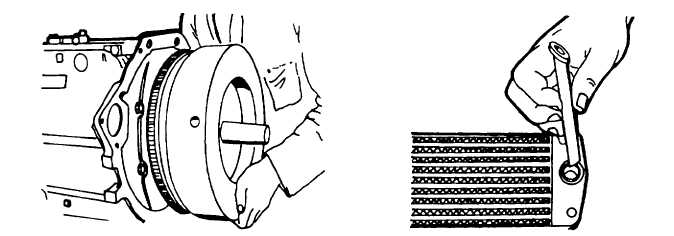
Check for pressure of the key for the flywheel. The taper must be dry and free from grease. Insert mandrel No.
003-0674 in the crankshaft and mount the flywheel so that its groove engages the key (figure 5-38).
51.
Position the flywheel, torque the nut in accordance with Appendix F (use hammer spanner No. 003-0503).
52.
Install the V-belt pulley. The cutout portion of the front end must be in alignment with the key in the crankshaft
gear wheel.
53.
Position the flywheel; torque the nuts securing the V-belt pulley in accordance with Appendix F (use retainer for
V-belt pulley No. 003-0446).
54.
Place a new rubber 0-seal, coated with grease, in the joint face of the oil cooler and insert the plain end of the oil
pipe in the oil cooler (figure 5-39).
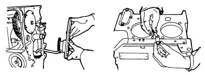
Figure 5-36. Mounting Front Cover with
Figure 5-37. Assembling Threaded Sleeve
Lube Oil Pump
to Middle Screw
Figure 5-38. Installing Flywheel
Figure 5-39. Installing Oil Pipe
into Oil Cooler
5-24


